66
02-1491-00-11.fm
Operation
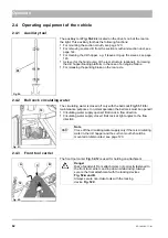
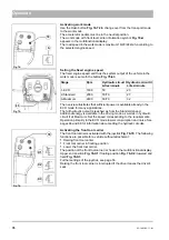
Output setting for hydraulic circuit I
The maximum delivery of hydraulic circuit I is determined by the coding
plugs on the attachment. Two selectable oil flows with a maximum flow of
50 l/min (
Fig. 58-A
) or 70 l/min (
Fig. 58-B
) are available for attachments
without coding plugs. The adjustment is made on the configuration menu,
see page 41.
In the working menu, the hydraulic circuit I
Fig. 58-A
is activated and set
to the required value with the turn-push knob
Fig. 58-69
. Setting range:
OFF/ON or 0 to 100 % In the setting to 70 l/min the adjustment process
stops initially at 70 % (corresponds to 50 l/min setting), but can be contin-
ued by renewed turning of
Fig. 58-69
up to 100 % (70 l/min).
63
Fig. 58:
B
A
69
C
Danger
Risk of injury! Make sure that the attachments are suitable for
the set oil volume. An oil volume set too high can lead to inju-
ries due to a defect of the attachment! As a reminder, the set-
ting process is interrupted briefly at 70 %.
Note
The hydraulic circuit I is switched off if the driver leaves the
driver's seat. The driver switches the hydraulic circuit I back
on with
Fig. 58-69
after returning to the driver's seat. In con-
nection with the sweeping unit and the universal hopper, the
brush is restarted by pushing the left joystick to the front!
Note
The delivery of hydraulic circuit I depends to a large extent on
the engine speed set on the tip switch
Fig. 58-63
. Select the
ECO mode as often as possible in the sense of the most
energy-saving operation of the vehicle.
If the oil flow requested by
Fig. 58-69
does not reach the set
value, then the warning
Fig. 58-C
appears in the multifunc-
tional display. Cancel the adjustment or increase the engine
speed until the warning symbol goes out. Also increase the
engine speed if you require additional power for driving (e.g.
driving uphill or propulsion work in winter service). If the addi-
tional power requirement is no longer required, reduce the
power step by step.
Содержание Citymaster 1600
Страница 22: ...22 01 1491 00 12 fm Safety Instructions G A B D E F Fig 3 C F C E C D G A B A...
Страница 26: ...26 02 1491 00 11 fm Operation Fig 5 25 23 16 18 17 19 22 21 20 24 26 27...
Страница 28: ...28 02 1491 00 11 fm Operation Fig 6 28 42 44 41 43 46 47 37 36 38 39 40 35 41 48 49 34 30 32 29 33 31 45...
Страница 30: ...30 02 1491 00 11 fm Operation Fig 7 62 63 61 67 55 50 51 54 53 52 58 57 59 60 65 64 66 68 56...
Страница 32: ...32 02 1491 00 11 fm Operation Fig 8 75 69 78 73 72 79 80 81 82 83 74 77 70 71 76 84...
Страница 85: ...04 1491 00 11 fm 85 Technical Data 4 Technical Data Fig 80 3830 1600 941 1210 975 1964...
Страница 146: ...146 06 1491 00 12 fm Attachments and Options 6 1 5 Technical data Fig 144 2215 4510 1580 2250...
Страница 220: ...220 06 1491 00 12 fm Attachments and Options...


