126
06-1491-00-12.fm
Attachments and Options
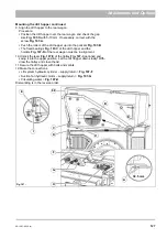
Continued – Mounting the dirt hopper
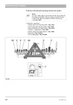
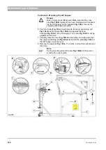
6 Push the trolley
Fig. 106-J
(optional) with the lower positioning aid
into the spars
and against the fixed
bearings
Fig. 106-H
of the dirt hopper. The screw
Fig. 106-F
must be
adjusted to 38.5 mm!
7 Carefully lower the lever
of the trolley and make sure that
the upper positioning aid
Fig. 106-I
sits behind the plate
of
the dirt hopper. Lock the lever.
8 Remove the supports
. To do this, pull out the split pins and
the bolts.
Danger
Risk of injury due to tilting over! Make sure that the cross
strut
(optional) has been inserted when transport-
ing the dirt hopper on the supports
. Secure the
supports with bolts and splints.
Note
During mounting protect the seal
of the suction
mouth with a cover plate.
Fig. 106:
88
H
B
A
I
J
E
C
G
38.5 mm
F
K
D
J
L
Содержание Citymaster 1600
Страница 22: ...22 01 1491 00 12 fm Safety Instructions G A B D E F Fig 3 C F C E C D G A B A...
Страница 26: ...26 02 1491 00 11 fm Operation Fig 5 25 23 16 18 17 19 22 21 20 24 26 27...
Страница 28: ...28 02 1491 00 11 fm Operation Fig 6 28 42 44 41 43 46 47 37 36 38 39 40 35 41 48 49 34 30 32 29 33 31 45...
Страница 30: ...30 02 1491 00 11 fm Operation Fig 7 62 63 61 67 55 50 51 54 53 52 58 57 59 60 65 64 66 68 56...
Страница 32: ...32 02 1491 00 11 fm Operation Fig 8 75 69 78 73 72 79 80 81 82 83 74 77 70 71 76 84...
Страница 85: ...04 1491 00 11 fm 85 Technical Data 4 Technical Data Fig 80 3830 1600 941 1210 975 1964...
Страница 146: ...146 06 1491 00 12 fm Attachments and Options 6 1 5 Technical data Fig 144 2215 4510 1580 2250...
Страница 220: ...220 06 1491 00 12 fm Attachments and Options...


