64
02-1491-00-11.fm
Operation
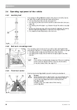
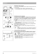
Adjusting the lowering valve
The lowering valve
is used to adjust the lowering speed of the
front tool carrier.
•
Turn the lowering valve clockwise = lowering speed lower
•
Turn the lowering valve counter-clockwise = lowering speed higher
Adjustable upper link (optional)
The adjustable upper link
Fig. 55-A
is provided for the fine adjustment of
attachments and for simplified take-up of attachments with conventional
A-frames type 0. Loosen the nut
and adjust the middle section
with a suitable tool to the required length. Then secure with the nut
Fig. 55-B
.
•
Turn the middle section clockwise = the front tool carrier inclines to the
front
•
Turn the middle section counter-clockwise = the front tool carrier
inclines to the back
Maximum
(I)
: The spindle touches the edges of the long elongated hole.
Minimum
(II)
: both spindles are flush
Standard length
(III)
: The spindle touches the edges of the short elon-
gated hole.
Lift system tipper body (optional)
With the optional lift system tipper body, additional controls for raising or
lowering the tipper body are located on the left side of the rear wagon.
•
Raise tipper body: Press the button
and the button
Fig. 56-B
simultaneously
•
Lower tipper body: Press the button
Fig. 56-A
and the button
Fig. 56-C
simultaneously
Fig. 54:
Fig. 55:
A
B
II
I
III
Note
When the sweeping system is used, adjustment to position III
is required for correct operation of the sweeping unit.
A
Fig. 56:
B
C
Danger
Risk of crushing! When carrying out work on the tipper body,
always operate the controls in two-handed operation.
Содержание Citymaster 1600
Страница 22: ...22 01 1491 00 12 fm Safety Instructions G A B D E F Fig 3 C F C E C D G A B A...
Страница 26: ...26 02 1491 00 11 fm Operation Fig 5 25 23 16 18 17 19 22 21 20 24 26 27...
Страница 28: ...28 02 1491 00 11 fm Operation Fig 6 28 42 44 41 43 46 47 37 36 38 39 40 35 41 48 49 34 30 32 29 33 31 45...
Страница 30: ...30 02 1491 00 11 fm Operation Fig 7 62 63 61 67 55 50 51 54 53 52 58 57 59 60 65 64 66 68 56...
Страница 32: ...32 02 1491 00 11 fm Operation Fig 8 75 69 78 73 72 79 80 81 82 83 74 77 70 71 76 84...
Страница 85: ...04 1491 00 11 fm 85 Technical Data 4 Technical Data Fig 80 3830 1600 941 1210 975 1964...
Страница 146: ...146 06 1491 00 12 fm Attachments and Options 6 1 5 Technical data Fig 144 2215 4510 1580 2250...
Страница 220: ...220 06 1491 00 12 fm Attachments and Options...


