


Page 153
Warning!
A torque screwdriver calibrated to 1.2 Nm (120 Ncm) is required for the correct
service of the Mixer Reactor. It is strongly recommended not to proceed with the Mixer
Reactor service procedures without a torque screwdriver.
Tools Required
– Torque Screwdriver with Torx 20 bit. An adjustable torque screwdriver can
be obtained from a local supplier. Example specifications and suppliers of the torque
screwdriver are as follows:
Lindstrom adjustable torque driver, 40-200Ncm
Stanley Supply & Services, Inc.
http://www.stanleysupplyservices.com/product-detail.aspx?pn=419-704
RS Components Ltd.
http://uk.rs-online.com/web/p/torque-drivers/3851794/
Remove the screws on the front of the Mixer Reactor and remove the reactor motor at the
back. Hold the reactor diaphragm carefully using both hands and turn the diaphragm anti-
clockwise to unscrew. It is recommended to count the number of turns by putting a small
mark on the diaphragm during this process. Using both hands screw in the new diaphragm
(
see item C7 in the service kit
) and tighten it firmly. The typical minimum number of turns to
tighten the diaphragm is from 7 to 8.5 turns. If a minimum number of 7 turns, or the number
of turns counted above when the old diaphragm was removed, is not achieved, the
diaphragm must be removed and reinstalled. Push the edge of the diaphragm down firmly
into place. When the installation of the diaphragm is complete, confirm that the diaphragm
forms a “concave” shape at the center. In other words, when the diaphragm is installed
correctly, the diaphragm should curve in forming a dent at the center. If such dent has not
formed, unscrew the diaphragm, confirm that the diaphragm is installed correctly and if
necessary tighten the diaphragm more with additional turns. Install the reactor motor back
onto the Mixer Reactor and tighten the screws. The torque of the screws should not exceed
1.2 Nm (120 Ncm).
_____
Confirm that the temperature of the ozone destructor has dropped to ambient temperature
level. Open the ozone destructor. The ozone destructor should never be opened when it is
hot as the threads may seize. Confirm that the PTFE filters (discs) in the ozone destructor
are clean. If there is any material build up (e.g. white powder), wash the filters using DIW (or
tap water) and dry. Do not use compressed air or any gas to clean the filters.
_____
Replace the catalyst and glass wool in the ozone destructor
(see item C8 in the service kit).
_____
Replace the o-ring in the Ozone Destructor
(see item C6 in the service kit).
_____
Reconnect power to ozone destructor heater.
_____
Using the Simulate menu (see Section
for details) and referring to figure 1
, activate OZONE GENERATOR and
confirm that the Ozone Generator is working and current displayed on screen is 1.00 Amp
(±0.05 Amp). The normal warm running current should not exceed 1.1 Amp. If necessary
adjust the current using the Ozone Generator Current Adjustment Potentiometer located on
the Ozone Generator.
_____
Remove the tapes, which are used to seal the ends of the supplied CO
2
filter
(see item C9 in
the service kit)
. Replace the CO
2
filter on the Base reagent container. Seal the Base
container tightly.
_____
Isolate the air supply to the analyzer. Go to Simulate menu and set MFC to 60 l/h and run the
oxygen supply until the flow drops to 0 l/h (until the oxygen tank is empty). Install the new
Hepa Filter
(see item C10 in the service kit)
carefully without contaminating the open tubing.
Turn the air supply on.
_____
Содержание BioTector B3500C
Страница 17: ...Page 17 Software Menu Diagram...
Страница 44: ...Page 44 Figure 4 BioTector analysis layout typical TIC TOC system...
Страница 46: ...Page 46 Figure 6 BioTector oxygen concentrator layout...
Страница 63: ...Page 63...
Страница 78: ...Page 78 Section 8 Maintenance Menu Maintenance Menu Diagram...
Страница 155: ...Page 155 Section 11 System Replacement and Spare Parts...
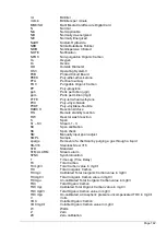
Страница 163: ...Page 163 ZK Zero check ZM Manually input zero adjust ZS Zero and Span...


