


Page 124
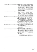
OUTPUT 1-6
OUTPUT 1-6 menus typically contain internal output settings
related to system operation. These relay outputs, located on the
Motherboard, are system optional features.
STREAM 1 is always functional as default within the system
software. OUTPUT 4-6 menus are not displayed as they are
reserved for future use.
OUTPUT 1-6 relays are programmed to a single output function
or to multiple output functions if the relevant option has been
installed in the BioTector. The programmed output function or
functions are marked with an asterisk “*” sign in these menus as
in the example for OUTPUT 1, which is programmed for
MAINTANENCE SIGNAL and CALIBRATION SIGNAL below.
When multiple functions are programmed for an output relay, the
relay output is activated when one or multiple conditions are
initiated. In the example below, OUTPUT 1 is activated when
MAINTANENCE SIGNAL or CALIBRATION SIGNAL is
triggered.
In BioTector configuration data download (or in All Data
download), the programmed output functions for each output is
tabulated and marked with asterisk “*” signs for clarity.
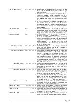
OUTPUT 1
DEFAULT STATE
N/D
DEFAULT STATE defines the idle state of the relay. N/D stands for “Normally De-
energized” relay by default and N/E stands for “Normally Energized” relay.
STOP
Output set to operate when the BioTector is stopped condition. Note that remote stand-
by is not considered as a stop condition.
FAULT
Output set to operate on fault condition.
WARNING
Output set to operate on warning condition.
NOTE
Output activated when a notification is logged in the fault archive.
SAMPLER FILL
Fill signal, sent to the sampler, which remains on from start of sampler fill time to the
completion of the sample injection.
SAMPLER EMPTY
Empty signal, sent to the sampler, which is a pulse of 5 seconds duration and is
triggered after the Sample Pump reverse operation is complete.
SAMPLER ERROR
Output when SAMPLER ERROR input signal is activated due to a sample error in the
BioTector Sampler.
SYNC
Synchronization relay, use to synchronize the system with external control units.
REMOTE STANDBY
Output when Remote Standby input is activated.
MAN MODE TRIG
Indicates that manual reactions are activated and going to be executed regardless of
the activation is carried out manually on the keyboard or remotely from a system input.
MAINT SIGNAL
*
Output when MAINTENANCE SWITCH input is activated.
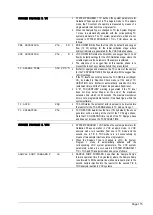
TEMP. SWITCH
Temperature Switch output activated when the temperature of the system increases
above the predefined system temperature control level (System Fan Control), which is
programmed as 20°C by default.
CAL
Calibration Valve used during calibration reactions.
CAL SIGNAL
*
Output set to operate on Zero/Span Check and Zero/Span Calibration reactions.
STREAM 1-3
Output set for Stream Valves 1-3.
MANUAL 1-3
Output set for Manual Valves 1-3.
SAMPLE STATUS 1-3
Digital output activated (energized) when BioTector Sample Sensor detects no sample
or when the sample quality is less than the default 95% threshold value for a specific
stream.
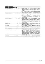
ALARM 1-3
Alarm relay, activated upon programmed alarm conditions for a specific stream.
CO2 ALARM 1-3
CO2 Alarm relay, activated upon programmed CO2 alarm conditions for a specific
stream.
4-20mA CHNG
4-20mA output change flag relay, which is always activated for a period of 10s, when a
new result causes update of any of the 4-20mA output channels.
4-20mA CHNG 1-3
4-20mA output change flag relay, which is always activated for a period of 10s, when a
new result causes update of a given 4-20mA output channels for a specific stream.
4-20mA READ
This signal is used to indicate valid/stable values on 4-20mA output channels in 4-
20mA Stream & Full Multiplex operation modes.
SAMPLE FAULT 1-3
Output when the external stream specific SAMPLE FAULT 1-3 input signal is activated.
Содержание BioTector B3500C
Страница 17: ...Page 17 Software Menu Diagram...
Страница 44: ...Page 44 Figure 4 BioTector analysis layout typical TIC TOC system...
Страница 46: ...Page 46 Figure 6 BioTector oxygen concentrator layout...
Страница 63: ...Page 63...
Страница 78: ...Page 78 Section 8 Maintenance Menu Maintenance Menu Diagram...
Страница 155: ...Page 155 Section 11 System Replacement and Spare Parts...
Страница 163: ...Page 163 ZK Zero check ZM Manually input zero adjust ZS Zero and Span...


