85
January 2004
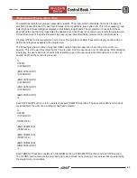
DIAGRAM Coordinates
Each of the elements of the diagram must have a starting point and an ending point. The notation is [X,Y]
where X is the horizontal coordinate and Y is the vertical coordinate. The best way to find out what the starting
and ending points should be is to use graph paper. First sketch, on the graph paper, what is to appear on the
screen. Then pick a point on the graph paper to be the origin, [0,0] (Any point will work, as the diagram will be
scaled to fit wherever it is drawn). You can then determine the starting and ending points of all the lines, arcs
(CW or CCW) and threads.
DIAGRAM Elements
The elements that make up a diagrams are lines, arcs (CW or CCW) and Threads. For each element, the
starting point is specified first, then the ending point.
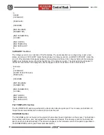
The format for a line is:
(LINE [X1,Y1] [X2,Y2])
The format for a clockwise arc is:
(CW [X1,Y1] [X2,Y2] r)
where r is the radius of the arc.
The format for a counterclockwise arc is:
(CCW [X1,Y1] [X2,Y2] r)
where r is the radius of the arc.
The format for a jagged line to represent a thread is;
(THREAD [X1,Y1] [X2,Y2])
NOTE
: Arcs (CW or CCW) may only cover 180 degrees, or half a circle. If an arc of more
than 180 degrees is needed, another arc must be used.
PARAMETERS Section
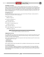
The PARAMETERS section lists all of the parameters that can be used to customize the standard part. Some
of these would be the physical dimensions of the raw material and the part. Others would be tool and offset
information, feed rates, and spindle speeds.
Each parameter begins with #, which tells Visual Quick Code that value followed by the # will be the name
for a specific variable. The format is:
(PARAMETERS)
(#your variable name)
(END PARAMETERS)
After a variable (parameter) has been specified, then any attributes of that particular parameter can be specified.
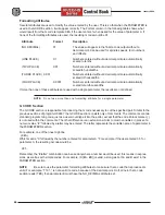
The POSITION Attribute
If you wish the parameter to appear in the diagram, you must supply a position. The format is (POSITION
[X,Y]), where X is the horizontal coordinate and Y is the vertical coordinate. These coordinates are relative to
the coordinates specified in the DIAGRAM section. Typically, only physical dimensions of the part will have a
POSITION attribute.
Содержание EC Series
Страница 1: ...January 2004 ...
Страница 7: ...V I January 2004 ...
Страница 125: ...118 January 2004 ...
Страница 126: ......

