30
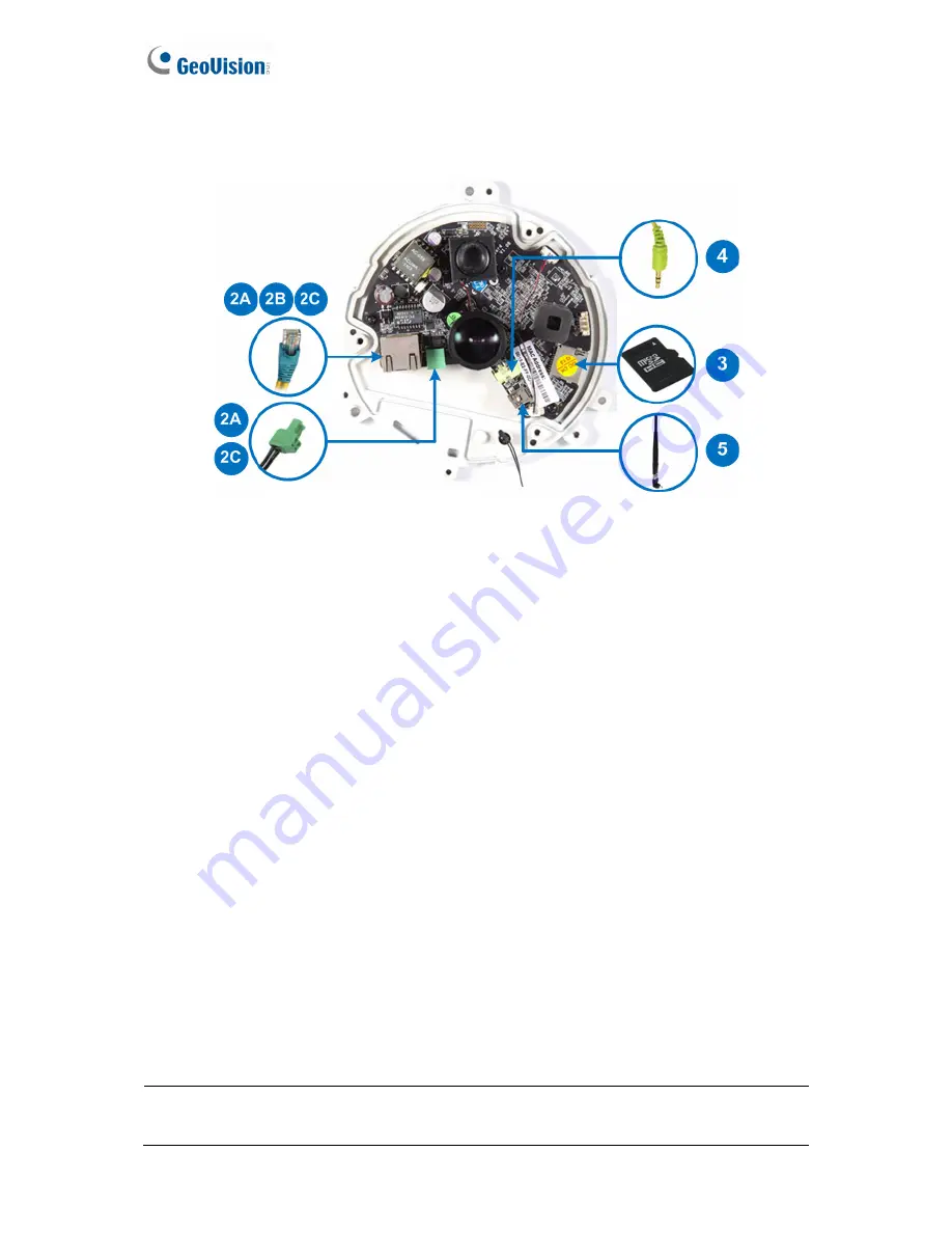
1.7.3 GV-FE2302 / 3402 / 3403 / 5302 / 5303
Figure 1-26
1. Remove the camera cover with the supplied torx wrench.
2. Supply power and network to the camera with one of the following methods:
A.
Power adapter:
plug in the power adapter and connect a standard network work
cable.
B.
Power over Ethernet (PoE):
connect the camera to a PoE switch with a standard
network cable to supply power and network.
C.
PoE Converter:
this method is only applicable to indoor GV-Fisheye Camera
installed with an IR LED ring (GV-FE3403 / 5303). A PoE converter allows the
camera to be connected to a PoE switch (thus supplied with network and power
over a network cable), and also supplies power to IR LED ring. For installation
steps, see
1.7.4 Connecting PoE Converter and IR LED Ring for GV-FE3403 /
5303
.
3. Optionally insert a micro SD card (SD/SDHC, version 2.0 only, Class 10).
4. Optionally connect an external speaker.
5. Optionally connect a GV-WiFi Adapter (for WiFi accessibility) or an external USB hard
drive (for additional storage).
6. Secure the camera cover with the supplied torx wrench.
Note:
For details on the limitations and requirements of mini USB port, refer to
Note for
USB Storage and WiFi Adapter
at the beginning of this manual.
Содержание GV-Fisheye
Страница 47: ...Introduction 33 1 5 Secure the PoE converter to the ceiling with 3 self prepared screws Figure 1 30 ...
Страница 52: ...38 4 The login page appears Figure 2 3 5 Type the default ID and password admin and click Apply to login ...
Страница 71: ...Accessing the Camera 57 3 Note The I O Control function is only supported by GV FE2301 421 4301 521 ...
Страница 89: ...Administrator Mode 75 4 4 1 1 Video Settings Figure 4 2A ...
Страница 90: ...76 Figure 4 2B ...
Страница 145: ...Administrator Mode 131 4 Figure 4 38 2 ...
Страница 146: ...132 4 8 5 Tools This section allows you to execute certain system operations and view the firmware version Figure 4 39 ...


