88
4.2 I/O Control
The I/O wires connected to the camera provide the interface for one input device and one
output device.
Note:
The I/O settings are only supported by GV-FE2301 / 421 / 4301 / 521.
4.2.1 Input Settings
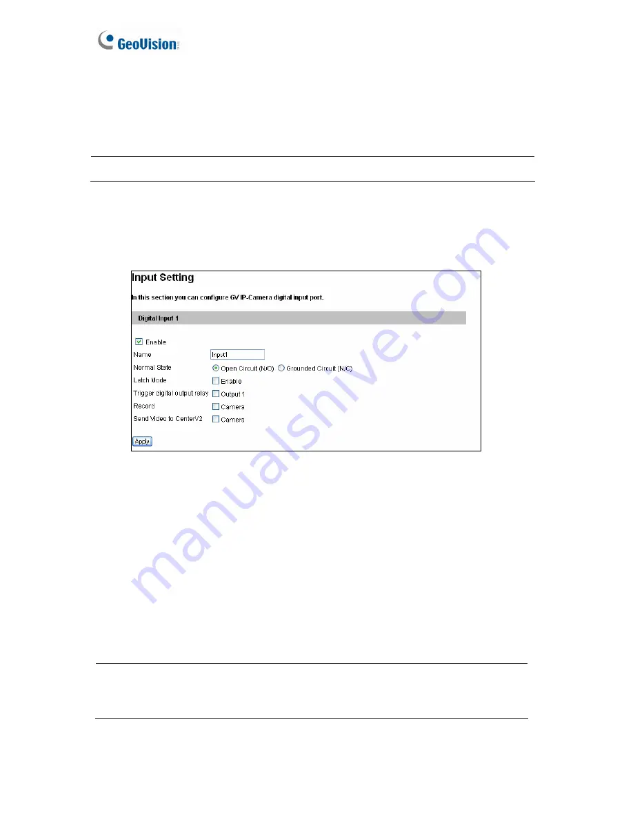
To activate the sensor input, select
Enable
.
Figure 4-11
Normal State:
You can set the input state to trigger actions by selecting
Open Circuit
(N/O)
or
Grounded Circuit (N/C)
.
Latch Mode:
Enable this option to have a momentary output alarm.
Trigger digital output relay:
When this option is enabled, the output will be triggered
once the input is activated.
Record:
Enable this option to start recording when the input is triggered.
Send Video to Center V2:
Enable this option to send the images to Center V2 when the
input is triggered.
Note:
Triggering the output, recording the images and sending video to Center V2 are
enabled only after you start
Input
monitoring manually or by schedule. To configure the
input monitoring, see
4.4 Monitoring
.
Содержание GV-Fisheye
Страница 47: ...Introduction 33 1 5 Secure the PoE converter to the ceiling with 3 self prepared screws Figure 1 30 ...
Страница 52: ...38 4 The login page appears Figure 2 3 5 Type the default ID and password admin and click Apply to login ...
Страница 71: ...Accessing the Camera 57 3 Note The I O Control function is only supported by GV FE2301 421 4301 521 ...
Страница 89: ...Administrator Mode 75 4 4 1 1 Video Settings Figure 4 2A ...
Страница 90: ...76 Figure 4 2B ...
Страница 145: ...Administrator Mode 131 4 Figure 4 38 2 ...
Страница 146: ...132 4 8 5 Tools This section allows you to execute certain system operations and view the firmware version Figure 4 39 ...


