R
ECONDITIONING
OI 250 (EN)
REV7
/REV7
10.1.8
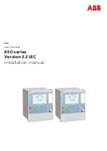
Connecting the Making and Breaking Units
The two lever arms of the guide lever are not identical. Matching
them up with the guide rods is facilitated by an identification sy-
stem.
Identification System
• Insert a new interrupter unit into the movable contact system until
it hits the stop. As you do so, insert the rods of the interrupter unit
through the large holes in the movable contact system.
• Lubricate new flanged coupling pins (9) per lubrication
specification L7.
• Insert the rods of the movable contact system into the guide
levers, selecting the lever arm
marked with a dot
.
• Insert the rods of the interrupter unit into the guide levers,
selecting the lever arm that is
not marked with a dot
.
• Insert a new flanged coupling pin (9) from the outside into the
rods and levers.
• Secure it with a new cotter pin (10). We recommend tool T101 for
installing the cotter pins.
Guide lever
Guide rod
Movable contact system
Dot mark
Dot mark
Interrupter unit
No dot mark
No dot mark
5
Interrupter unit
1x
6
Movable contact system
1x
8
Guide lever
2x
9
Flanged coupling pin, 6x24
4x
10
Cotter pin, 8x1.2
4x
5
6
8
10
9
B
A
-P
-PS
-8
Содержание GL 311 F3/4031 P/VE
Страница 2: ......
Страница 10: ...INTRODUCTION 10 146 OI 250 EN REV7 REV6...
Страница 12: ...SAFETY 12 146 OI 250 EN REV7 REV3...
Страница 48: ...INSTALLATION 48 146 OI 250 EN REV7 REV7...
Страница 80: ...INSPECTION AND MAINTENANCE 80 146 OI 250 EN REV7 REV3...
Страница 102: ...RECONDITIONING 102 146 OI 250 EN REV7 REV7...
Страница 104: ...END OF LIFE MANAGEMENT 104 146 OI 250 EN REV7 REV2a...
Страница 114: ...SPECIAL EQUIPMENT OPTIONAL 114 146 OI 250 EN REV7 REV0...
Страница 128: ...REPLACEMENT PARTS AND ACCESSORIES 128 146 OI 250 EN REV7 REV6...
Страница 130: ...HANDLING USED SULFUR HEXAFLUORIDE 130 146 OI 250 EN REV7 REV2...