GE Multilin
F60 Feeder Protection System
3-15
3 HARDWARE
3.2 WIRING
3
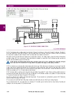
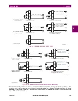
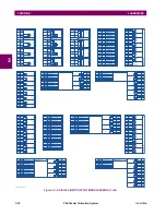
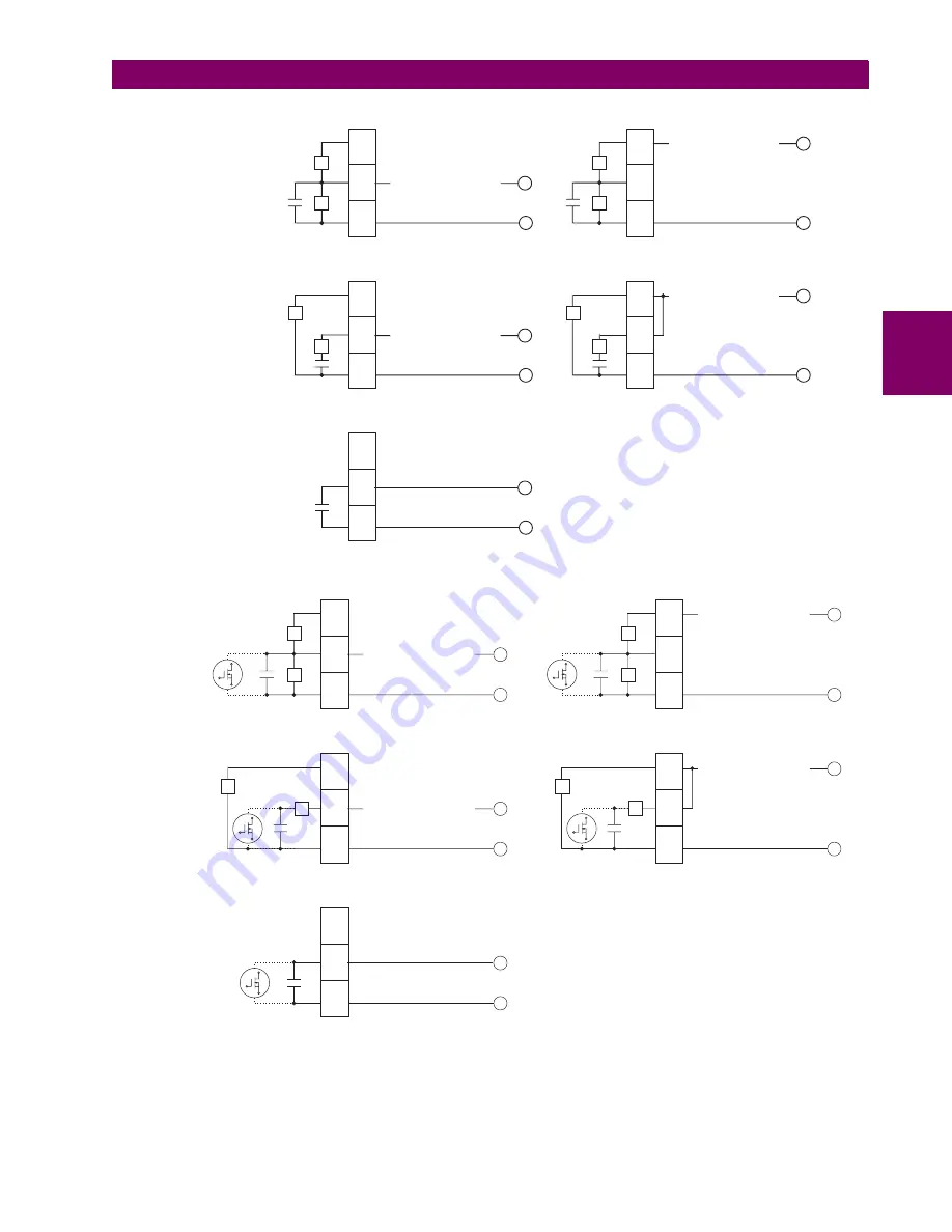
Figure 3–17: FORM-A CONTACT FUNCTIONS
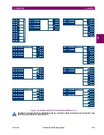
Figure 3–18: FORM-A AND SOLID STATE CONTACT FUNCTIONS
The operation of voltage and current monitors is reflected with the corresponding FlexLogic™ operands (
CONT OP # VON
,
CONT OP # VOFF
,
CONT OP # ION
, and
CONT OP # IOFF
) which can be used in protection, control and alarm logic. The typical
application of the voltage monitor is breaker trip circuit integrity monitoring; a typical application of the current monitor is
seal-in of the control command.
Load
I
~#a
+
-
~#b
~#c
If Idc
1mA, Cont Op xxx Von
otherwise Cont Op xxx Voff
³
V
827821A6.CDR
a) Voltage with optional
current monitoring
Voltage monitoring only
Load
I
+
-
V
Both voltage and current monitoring
If Idc
80mA, Cont Op xxx Ion
otherwise Cont Op xxx Ioff
³
If Idc
1mA, Cont Op xxx Von
otherwise Cont Op xxx Voff
³
Load
I
+
-
V
b) Current with optional
voltage monitoring
Current monitoring only
Both voltage and current monitoring
(external jumper a-b is required)
If Idc
80mA, Cont Op xxx Ion
otherwise Cont Op xxx Ioff
³
Load
I
-
V
+
If Idc
80mA, Cont Op xxx Ion
otherwise Cont Op xxx Ioff
³
If Idc
1mA, Cont Op xxx Von
otherwise Cont Op xxx Voff
³
Load
+
-
c) No monitoring
~#a
~#b
~#c
~#a
~#b
~#c
~#a
~#b
~#c
~#a
~#b
~#c
Load
I
~#a
~#b
~#c
If Idc
1mA,
otherwise
³
Cont Op ## Von
Cont Op ## Voff
V
827862A2.CDR
+
+
+
+
+
-
-
-
-
-
a) Voltage with optional
current monitoring
Voltage monitoring only
Load
I
V
Both voltage and current monitoring
If Idc
80mA,
otherwise
³
Cont Op ## Ion
Cont Op ## Ioff
If Idc
1mA,
otherwise
³
Cont Op ## Von
Cont Op ## Voff
Load
I
V
b) Current with optional
voltage monitoring
Current monitoring only
Both voltage and current monitoring
(external jumper a-b is required)
If Idc
80mA,
otherwise
³
Cont Op ## Ion
Cont Op ## Ioff
Load
V
If Idc
80mA,
otherwise
³
Cont Op ## Ion
Cont Op ## Ioff
If Idc
1mA,
otherwise
³
Cont Op ## Von
Cont Op ## Voff
Load
c) No monitoring
~#a
~#b
~#c
~#a
~#b
~#c
~#a
~#b
~#c
~#a
~#b
~#c
I
Содержание F60 UR Series
Страница 2: ......
Страница 4: ......
Страница 30: ...1 20 F60 Feeder Protection System GE Multilin 1 5 USING THE RELAY 1 GETTING STARTED 1 ...
Страница 48: ...2 18 F60 Feeder Protection System GE Multilin 2 2 SPECIFICATIONS 2 PRODUCT DESCRIPTION 2 ...
Страница 96: ...3 48 F60 Feeder Protection System GE Multilin 3 4 MANAGED ETHERNET SWITCH MODULES 3 HARDWARE 3 ...
Страница 126: ...4 30 F60 Feeder Protection System GE Multilin 4 2 FACEPLATE INTERFACE 4 HUMAN INTERFACES 4 ...
Страница 354: ...5 228 F60 Feeder Protection System GE Multilin 5 9 TESTING 5 SETTINGS 5 ...
Страница 382: ...6 28 F60 Feeder Protection System GE Multilin 6 5 PRODUCT INFORMATION 6 ACTUAL VALUES 6 ...
Страница 398: ...8 8 F60 Feeder Protection System GE Multilin 8 2 FAULT LOCATOR 8 THEORY OF OPERATION 8 ...
Страница 414: ...A 14 F60 Feeder Protection System GE Multilin A 1 PARAMETER LIST APPENDIXA A ...
Страница 492: ...B 78 F60 Feeder Protection System GE Multilin B 4 MEMORY MAPPING APPENDIXB B ...
Страница 530: ...D 10 F60 Feeder Protection System GE Multilin D 1 IEC 60870 5 104 APPENDIXD D ...
Страница 542: ...E 12 F60 Feeder Protection System GE Multilin E 2 DNP POINT LISTS APPENDIXE E ...
Страница 558: ...x F60 Feeder Protection System GE Multilin INDEX ...

