


5-198
F60 Feeder Protection System
GE Multilin
5.6 CONTROL ELEMENTS
5 SETTINGS
5
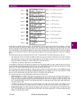
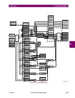
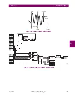
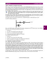
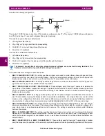
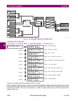
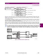
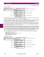
Figure 5–103: BREAKER RESTRIKE SCHEME LOGIC
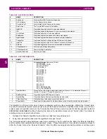
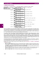
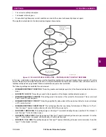
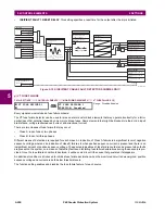
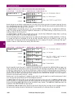
f) INCIPIENT FAULT DETECTOR
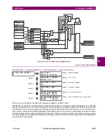
PATH: SETTINGS
ÖØ
CONTROL ELEMENTS
ÖØ
MONITORING ELEMENTS
ÖØ
INCIPIENT FAULT 1(2)
There are two incipient cable fault detection elements in the relay.
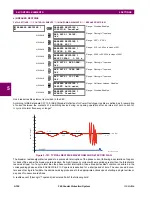
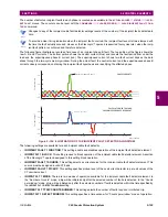
Before a permanent cable fault occurs, there are usually signs of degrading insulation manifesting itself as a short, mostly
half-cycle spikes asserting at the phase voltage peak. Due to shortness of such spikes, they are not usually detected by the
instantaneous protection of the feeder, which operates on the RMS or fundamental component of the phase current with a
relatively high pickup.
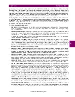
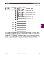
INCIPIENT FAULT 1
INCIPIENT FAULT 1
FUNCTION: Disabled
Range: Disabled, Enabled
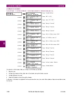
MESSAGE
INCIPNT FLT 1 BLOCK:
Off
Range: FlexLogic™ operand
MESSAGE
INCIPIENT FAULT 1
SOURCE: SRC 1
Range: SRC 1, SRC 2
MESSAGE
INCIPIENT FAULT 1
PICKUP: 0.50 pu
Range: 0.10 to 10.00 pu in steps of 0.01
MESSAGE
INCIPNT FLT 1 MODE:
Number of counts
Range: Number of counts, Counts per window
MESSAGE
INCIPIENT FLT 1 TRIP
COUNTS NUMBER: 2
Range: 1 to 10 in steps of 1
MESSAGE
INCIPNT FLT 1 DETECT
WINDOW: 10.00 s
Range: 0.00 to 1000.00 s in steps of 0.01
MESSAGE
INCIPIENT FAULT 1
RESET DELAY: 0.100 s
Range: 0.000 to 65.535 s in steps of 0.001
MESSAGE
INCIPIENT FAULT 1
TARGET: Self-reset
Range: Self-reset, Latched, Disabled
MESSAGE
INCIPIENT FAULT 1
EVENTS: Disabled
Range: Disabled, Enabled
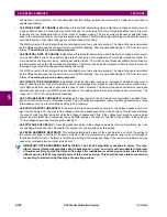
RUN
Current interruption
detection logic
< 0.05 pu
for > ¼ cycle
I
t
mag
ARMED
RESET
SETTING
= Enabled
BREAKER RESTRIKE 1
FUNCTION
SETTING
= Off
BKR RSTR 1 BLK
AND
SETTING
= IA
BREAKER RESTRIKE 1
SOURCE
= IB
= IC
SETTING
= Off
BKR RSTR 1 BKR OPEN
SETTING
= Off
BKR RSTR 1 OPEN CMD
SETTING
= Off
BKR RSTR 1 CLS CMD
AND
OR
SETTING
BREAKER RESTRIKE 1 PICKUP
RUN
Restrike detection logic
0
T
RST
SETTING
BREAKER RESTRIKE 1
RESET DELAY
0
T
RST
0
T
RST
FLEXLOGIC OPERANDS
BKR RESTRIKE 1 OP A
BKR RESTRIKE 1 OP B
BKR RESTRIKE 1 OP C
BKR RESTRIKE 1 OP
FLEXLOGIC OPERAND
OR
834012A1.CDR
Содержание F60 UR Series
Страница 2: ......
Страница 4: ......
Страница 30: ...1 20 F60 Feeder Protection System GE Multilin 1 5 USING THE RELAY 1 GETTING STARTED 1 ...
Страница 48: ...2 18 F60 Feeder Protection System GE Multilin 2 2 SPECIFICATIONS 2 PRODUCT DESCRIPTION 2 ...
Страница 96: ...3 48 F60 Feeder Protection System GE Multilin 3 4 MANAGED ETHERNET SWITCH MODULES 3 HARDWARE 3 ...
Страница 126: ...4 30 F60 Feeder Protection System GE Multilin 4 2 FACEPLATE INTERFACE 4 HUMAN INTERFACES 4 ...
Страница 354: ...5 228 F60 Feeder Protection System GE Multilin 5 9 TESTING 5 SETTINGS 5 ...
Страница 382: ...6 28 F60 Feeder Protection System GE Multilin 6 5 PRODUCT INFORMATION 6 ACTUAL VALUES 6 ...
Страница 398: ...8 8 F60 Feeder Protection System GE Multilin 8 2 FAULT LOCATOR 8 THEORY OF OPERATION 8 ...
Страница 414: ...A 14 F60 Feeder Protection System GE Multilin A 1 PARAMETER LIST APPENDIXA A ...
Страница 492: ...B 78 F60 Feeder Protection System GE Multilin B 4 MEMORY MAPPING APPENDIXB B ...
Страница 530: ...D 10 F60 Feeder Protection System GE Multilin D 1 IEC 60870 5 104 APPENDIXD D ...
Страница 542: ...E 12 F60 Feeder Protection System GE Multilin E 2 DNP POINT LISTS APPENDIXE E ...
Страница 558: ...x F60 Feeder Protection System GE Multilin INDEX ...