


GE Multilin
F60 Feeder Protection System
5-137
5 SETTINGS
5.5 GROUPED ELEMENTS
5
•
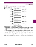
NEG SEQ DIR OC1 OFFSET:
This setting specifies the offset impedance used by this protection. The primary applica-
tion for the offset impedance is to guarantee correct identification of fault direction on series compensated lines (see
the
Application of settings
chapter for information on how to calculate this setting). In regular applications, the offset
impedance ensures proper operation even if the negative-sequence voltage at the relaying point is very small. If this is
the intent, the offset impedance shall not be larger than the negative-sequence impedance of the protected circuit.
Practically, it shall be several times smaller. The offset impedance shall be entered in secondary ohms. See the
Theory
of operation
chapter for additional details.
•
NEG SEQ DIR OC1 TYPE:
This setting selects the operating mode for the overcurrent unit of the element. The
choices are “Neg Sequence” and “Zero Sequence”. In some applications it is advantageous to use a directional nega-
tive-sequence overcurrent function instead of a directional zero-sequence overcurrent function as inter-circuit mutual
effects are minimized.
•
NEG SEQ DIR OC1 POS-SEQ RESTRAINT
: This setting controls the amount of the positive-sequence restraint. Set
to 0.063 (in “Zero Sequence” mode) or 0.125 (in “Neg Sequence” mode) for backward compatibility with revisions 3.40
and earlier. Set to zero to remove the restraint. Set higher if large system unbalances or poor CT performance are
expected.
•
NEG SEQ DIR OC1 FWD ECA:
This setting select the element characteristic angle (ECA) for the forward direction.
The element characteristic angle in the reverse direction is the angle set for the forward direction shifted by 180°.
•
NEG SEQ DIR OC1 FWD LIMIT ANGLE:
This setting defines a symmetrical (in both directions from the ECA) limit
angle for the forward direction.
•
NEG SEQ DIR OC1 FWD PICKUP:
This setting defines the pickup level for the overcurrent unit in the forward direc-
tion. Upon
NEG SEQ DIR OC1 TYPE
selection, this pickup threshold applies to zero- or negative-sequence current. When
selecting this setting it must be kept in mind that the design uses a
positive-sequence restraint
technique.
•
NEG SEQ DIR OC1 REV LIMIT ANGLE:
This setting defines a symmetrical (in both directions from the ECA) limit
angle for the reverse direction.
•
NEG SEQ DIR OC1 REV PICKUP:
This setting defines the pickup level for the overcurrent unit in the reverse direc-
tion. Upon
NEG SEQ DIR OC1 TYPE
selection, this pickup threshold applies to zero- or negative-sequence current. When
selecting this setting it must be kept in mind that the design uses a
positive-sequence restraint
technique.
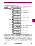
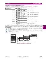
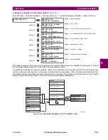
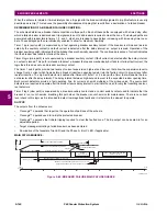
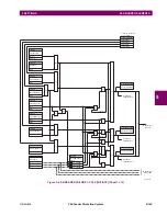
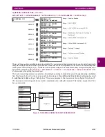
Figure 5–65: NEGATIVE SEQUENCE DIRECTIONAL OC1 SCHEME LOGIC
FLEXLOGIC OPERAND
FLEXLOGIC OPERAND
SETTING
SETTING
SETTING
SETTING
SETTINGS
SETTING
SETTING
NEG SEQ DIR OC1
FUNCTION:
NEG SEQ DIR OC1
SOURCE:
NEG SEQ DIR OC1
TYPE:
NEG SEQ DIR OC1 BLK:
NEG SEQ DIR OC1 FWD
LIMIT ANGLE:
NEG SEQ DIR OC1 REV
LIMIT ANGLE:
NEG SEQ DIR OC1
OFFSET:
NEG SEQ DIR OC1 FWD
ECA:
NEG SEQ DIR OC1 FWD
PICKUP:
NEG SEQ DIR OC1 REV
PICKUP:
NEG SEQ DIR OC1 FWD
NEG SEQ DIR OC1 REV
Disabled=0
Neg Seq Seq Crt (I_2)
Neg Seq Voltage (V_2)
Neg Sequence
Zero Seq Seq Crt (I_0)
Zero Sequence
827091A4.CDR
Off=0
Enabled=1
AND
AND
AND
AND
AND
AND
AND
AND
AND
OR
OR
I
I
_2 - K _1 PICKUP
I
I
_2 - K _1 PICKUP
I
I
_0 - K _1 PICKUP
I
I
_0 - K _1 PICKUP
Voltage Polarization
V_2 pol
FWD
FWD
REV
REV.
RUN
RUN
RUN
RUN
RUN
1.25 cy
1.5 cy
NEG SEQ DIR OC1 POS-
SEQ RESTRAINT:
NEG SEQ DIR OC1 POS-
SEQ RESTRAINT:
Содержание F60 UR Series
Страница 2: ......
Страница 4: ......
Страница 30: ...1 20 F60 Feeder Protection System GE Multilin 1 5 USING THE RELAY 1 GETTING STARTED 1 ...
Страница 48: ...2 18 F60 Feeder Protection System GE Multilin 2 2 SPECIFICATIONS 2 PRODUCT DESCRIPTION 2 ...
Страница 96: ...3 48 F60 Feeder Protection System GE Multilin 3 4 MANAGED ETHERNET SWITCH MODULES 3 HARDWARE 3 ...
Страница 126: ...4 30 F60 Feeder Protection System GE Multilin 4 2 FACEPLATE INTERFACE 4 HUMAN INTERFACES 4 ...
Страница 354: ...5 228 F60 Feeder Protection System GE Multilin 5 9 TESTING 5 SETTINGS 5 ...
Страница 382: ...6 28 F60 Feeder Protection System GE Multilin 6 5 PRODUCT INFORMATION 6 ACTUAL VALUES 6 ...
Страница 398: ...8 8 F60 Feeder Protection System GE Multilin 8 2 FAULT LOCATOR 8 THEORY OF OPERATION 8 ...
Страница 414: ...A 14 F60 Feeder Protection System GE Multilin A 1 PARAMETER LIST APPENDIXA A ...
Страница 492: ...B 78 F60 Feeder Protection System GE Multilin B 4 MEMORY MAPPING APPENDIXB B ...
Страница 530: ...D 10 F60 Feeder Protection System GE Multilin D 1 IEC 60870 5 104 APPENDIXD D ...
Страница 542: ...E 12 F60 Feeder Protection System GE Multilin E 2 DNP POINT LISTS APPENDIXE E ...
Страница 558: ...x F60 Feeder Protection System GE Multilin INDEX ...