


5-194
F60 Feeder Protection System
GE Multilin
5.6 CONTROL ELEMENTS
5 SETTINGS
5
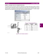
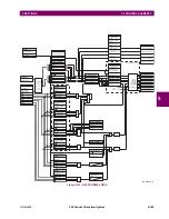
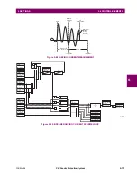
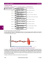
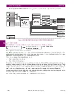
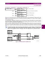
Consider the following configuration:
The source 1 (SRC1) phase currents are CTs and phase voltages are bus VTs. The source 2 (SRC2) phase voltages are
line VTs. Contact input 1 is set as the breaker 52a contact (optional).
The conditions prior to flashover detection are:
1.
Δ
VA is greater than pickup
2.
VAg, VBg, or VCg is greater than the pickup setting
3.
IA, IB, IC = 0; no current flows through the breaker
4.
52a status = 0 (optional)
The conditions at flashover detection are:
1.
Δ
VA is less than pickup
2.
VAg, VBg, or VCg is lower than the pickup setting
3.
IA, IB, or IC is greater than the pickup current flowing through the breaker
4.
52a status = 0 (optional)
The element is operational only when phase-to-ground voltages are connected to relay terminals. The
flashover element will not operate if delta voltages are applied.
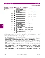
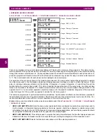
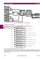
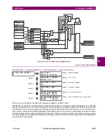
The breaker flashover settings are described below.
•
BRK 1 FLSHOVR SIDE 1 SRC
: This setting specifies a signal source used to provide three-phase voltages and three-
phase currents from one side of the current breaker. The source selected as a setting and must be configured with
breaker phase voltages and currents, even if only three (3) VTs are available across the breaker.
•
BRK 1 FLSHOVR SIDE 2 SRC
: This setting specifies a signal source used to provide another set of three phase volt-
ages whenever six (6) VTs are available across the breaker.
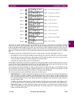
•
BRK 1 STATUS CLSD A
to
BRK 1 STATUS CLSD C
: These settings specify FlexLogic™ operands to indicate the
open status of the breaker. A separate FlexLogic™ operand can be selected to detect individual breaker pole status
and provide flashover detection. The recommended setting is 52a breaker contact or another operand defining the
breaker poles open status.
•
BRK 1 FLSHOVR V PKP
: This setting specifies a pickup level for the phase voltages from both sides of the breaker. If
six VTs are available, opening the breaker leads to two possible combinations – live voltages from only one side of the
breaker, or live voltages from both sides of the breaker. Either case will set the scheme ready for flashover detection
upon detection of voltage above the selected value. Set
BRK FLSHOVR V PKP
to 85 to 90% of the nominal voltage.
•
BRK 1 FLSHOVR DIFF V PKP
: This setting specifies a pickup level for the phase voltage difference when two VTs per
phase are available across the breaker. The pickup voltage difference should be below the monitored voltage differ-
ence when close or open breaker resistors are left in service. The setting is selected as primary volts difference
between the sources.
•
BRK 1 FLSHOVR AMP PKP
: This setting specifies the normal load current which can flow through the breaker.
Depending on the flashover protection application, the flashover current can vary from levels of the charging current
when the line is de-energized (all line breakers open), to well above the maximum line (feeder) load (line/feeder con-
nected to load).
•
BRK 1 FLSHOVR SPV A
to
BRK 1 FLSHOVR SPV C
: These settings specifiy FlexLogic™ operands (per breaker
pole) that supervise the operation of the element per phase. Supervision can be provided by operation of other protec-
842745A1.CDR
VTs
VTs
Line/Feeder
Breaker
CTs
Bus
NOTE
Содержание F60 UR Series
Страница 2: ......
Страница 4: ......
Страница 30: ...1 20 F60 Feeder Protection System GE Multilin 1 5 USING THE RELAY 1 GETTING STARTED 1 ...
Страница 48: ...2 18 F60 Feeder Protection System GE Multilin 2 2 SPECIFICATIONS 2 PRODUCT DESCRIPTION 2 ...
Страница 96: ...3 48 F60 Feeder Protection System GE Multilin 3 4 MANAGED ETHERNET SWITCH MODULES 3 HARDWARE 3 ...
Страница 126: ...4 30 F60 Feeder Protection System GE Multilin 4 2 FACEPLATE INTERFACE 4 HUMAN INTERFACES 4 ...
Страница 354: ...5 228 F60 Feeder Protection System GE Multilin 5 9 TESTING 5 SETTINGS 5 ...
Страница 382: ...6 28 F60 Feeder Protection System GE Multilin 6 5 PRODUCT INFORMATION 6 ACTUAL VALUES 6 ...
Страница 398: ...8 8 F60 Feeder Protection System GE Multilin 8 2 FAULT LOCATOR 8 THEORY OF OPERATION 8 ...
Страница 414: ...A 14 F60 Feeder Protection System GE Multilin A 1 PARAMETER LIST APPENDIXA A ...
Страница 492: ...B 78 F60 Feeder Protection System GE Multilin B 4 MEMORY MAPPING APPENDIXB B ...
Страница 530: ...D 10 F60 Feeder Protection System GE Multilin D 1 IEC 60870 5 104 APPENDIXD D ...
Страница 542: ...E 12 F60 Feeder Protection System GE Multilin E 2 DNP POINT LISTS APPENDIXE E ...
Страница 558: ...x F60 Feeder Protection System GE Multilin INDEX ...