


5-84
F60 Feeder Protection System
GE Multilin
5.4 FLEXLOGIC™
5 SETTINGS
5
5.4FLEXLOGIC™
5.4.1 INTRODUCTION TO FLEXLOGIC™
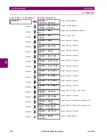
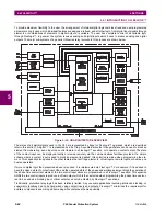
To provide maximum flexibility to the user, the arrangement of internal digital logic combines fixed and user-programmed
parameters. Logic upon which individual features are designed is fixed, and all other logic, from digital input signals through
elements or combinations of elements to digital outputs, is variable. The user has complete control of all variable logic
through FlexLogic™. In general, the system receives analog and digital inputs which it uses to produce analog and digital
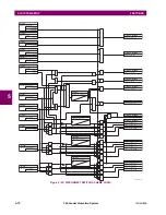
outputs. The major sub-systems of a generic UR-series relay involved in this process are shown below.
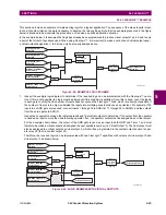
Figure 5–34: UR ARCHITECTURE OVERVIEW
The states of all digital signals used in the F60 are represented by flags (or FlexLogic™ operands, which are described
later in this section). A digital “1” is represented by a 'set' flag. Any external contact change-of-state can be used to block an
element from operating, as an input to a control feature in a FlexLogic™ equation, or to operate a contact output. The state
of the contact input can be displayed locally or viewed remotely via the communications facilities provided. If a simple
scheme where a contact input is used to block an element is desired, this selection is made when programming the ele-
ment. This capability also applies to the other features that set flags: elements, virtual inputs, remote inputs, schemes, and
human operators.
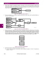
If more complex logic than presented above is required, it is implemented via FlexLogic™. For example, if it is desired to
have the closed state of contact input H7a and the operated state of the phase undervoltage element block the operation of
the phase time overcurrent element, the two control input states are programmed in a FlexLogic™ equation. This equation
ANDs the two control inputs to produce a virtual output which is then selected when programming the phase time overcur-
rent to be used as a blocking input. Virtual outputs can only be created by FlexLogic™ equations.
Traditionally, protective relay logic has been relatively limited. Any unusual applications involving interlocks, blocking, or
supervisory functions had to be hard-wired using contact inputs and outputs. FlexLogic™ minimizes the requirement for
auxiliary components and wiring while making more complex schemes possible.
Содержание F60 UR Series
Страница 2: ......
Страница 4: ......
Страница 30: ...1 20 F60 Feeder Protection System GE Multilin 1 5 USING THE RELAY 1 GETTING STARTED 1 ...
Страница 48: ...2 18 F60 Feeder Protection System GE Multilin 2 2 SPECIFICATIONS 2 PRODUCT DESCRIPTION 2 ...
Страница 96: ...3 48 F60 Feeder Protection System GE Multilin 3 4 MANAGED ETHERNET SWITCH MODULES 3 HARDWARE 3 ...
Страница 126: ...4 30 F60 Feeder Protection System GE Multilin 4 2 FACEPLATE INTERFACE 4 HUMAN INTERFACES 4 ...
Страница 354: ...5 228 F60 Feeder Protection System GE Multilin 5 9 TESTING 5 SETTINGS 5 ...
Страница 382: ...6 28 F60 Feeder Protection System GE Multilin 6 5 PRODUCT INFORMATION 6 ACTUAL VALUES 6 ...
Страница 398: ...8 8 F60 Feeder Protection System GE Multilin 8 2 FAULT LOCATOR 8 THEORY OF OPERATION 8 ...
Страница 414: ...A 14 F60 Feeder Protection System GE Multilin A 1 PARAMETER LIST APPENDIXA A ...
Страница 492: ...B 78 F60 Feeder Protection System GE Multilin B 4 MEMORY MAPPING APPENDIXB B ...
Страница 530: ...D 10 F60 Feeder Protection System GE Multilin D 1 IEC 60870 5 104 APPENDIXD D ...
Страница 542: ...E 12 F60 Feeder Protection System GE Multilin E 2 DNP POINT LISTS APPENDIXE E ...
Страница 558: ...x F60 Feeder Protection System GE Multilin INDEX ...