1-4
F60 Feeder Protection System
GE Multilin
1.2 UR OVERVIEW
1 GETTING STARTED
1
c) UR SCAN OPERATION
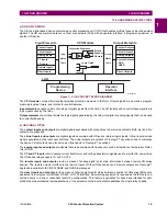
The UR-series devices operate in a cyclic scan fashion. The device reads the inputs into an input status table, solves the
logic program (FlexLogic™ equation), and then sets each output to the appropriate state in an output status table. Any
resulting task execution is priority interrupt-driven.
Figure 1–3: UR-SERIES SCAN OPERATION
1.2.3 SOFTWARE ARCHITECTURE
The firmware (software embedded in the relay) is designed in functional modules which can be installed in any relay as
required. This is achieved with object-oriented design and programming (OOD/OOP) techniques.
Object-oriented techniques involve the use of
objects
and
classes
. An object is defined as “a logical entity that contains
both data and code that manipulates that data”. A class is the generalized form of similar objects. By using this concept,
one can create a protection class with the protection elements as objects of the class, such as time overcurrent, instanta-
neous overcurrent, current differential, undervoltage, overvoltage, underfrequency, and distance. These objects represent
completely self-contained software modules. The same object-class concept can be used for metering, input/output control,
hmi, communications, or any functional entity in the system.
Employing OOD/OOP in the software architecture of the F60 achieves the same features as the hardware architecture:
modularity, scalability, and flexibility. The application software for any UR-series device (for example, feeder protection,
transformer protection, distance protection) is constructed by combining objects from the various functionality classes. This
results in a
common look and feel
across the entire family of UR-series platform-based applications.
1.2.4 IMPORTANT CONCEPTS
As described above, the architecture of the UR-series relays differ from previous devices. To achieve a general understand-
ing of this device, some sections of Chapter 5 are quite helpful. The most important functions of the relay are contained in
“elements”. A description of the UR-series elements can be found in the
Introduction to elements
section in chapter 5.
Examples of simple elements, and some of the organization of this manual, can be found in the
Control elements
section of
chapter 5. An explanation of the use of inputs from CTs and VTs is in the
Introduction to AC sources
section in chapter 5. A
description of how digital signals are used and routed within the relay is contained in the
Introduction to FlexLogic™
section
in chapter 5.
827823A1.CDR
PKP
DPO
OP
Protective Elements
Protection elements
serviced by sub-scan
Read Inputs
Solve Logic
Set Outputs
Содержание F60 UR Series
Страница 2: ......
Страница 4: ......
Страница 30: ...1 20 F60 Feeder Protection System GE Multilin 1 5 USING THE RELAY 1 GETTING STARTED 1 ...
Страница 48: ...2 18 F60 Feeder Protection System GE Multilin 2 2 SPECIFICATIONS 2 PRODUCT DESCRIPTION 2 ...
Страница 96: ...3 48 F60 Feeder Protection System GE Multilin 3 4 MANAGED ETHERNET SWITCH MODULES 3 HARDWARE 3 ...
Страница 126: ...4 30 F60 Feeder Protection System GE Multilin 4 2 FACEPLATE INTERFACE 4 HUMAN INTERFACES 4 ...
Страница 354: ...5 228 F60 Feeder Protection System GE Multilin 5 9 TESTING 5 SETTINGS 5 ...
Страница 382: ...6 28 F60 Feeder Protection System GE Multilin 6 5 PRODUCT INFORMATION 6 ACTUAL VALUES 6 ...
Страница 398: ...8 8 F60 Feeder Protection System GE Multilin 8 2 FAULT LOCATOR 8 THEORY OF OPERATION 8 ...
Страница 414: ...A 14 F60 Feeder Protection System GE Multilin A 1 PARAMETER LIST APPENDIXA A ...
Страница 492: ...B 78 F60 Feeder Protection System GE Multilin B 4 MEMORY MAPPING APPENDIXB B ...
Страница 530: ...D 10 F60 Feeder Protection System GE Multilin D 1 IEC 60870 5 104 APPENDIXD D ...
Страница 542: ...E 12 F60 Feeder Protection System GE Multilin E 2 DNP POINT LISTS APPENDIXE E ...
Страница 558: ...x F60 Feeder Protection System GE Multilin INDEX ...


