


556
D90
PLUS
LINE DISTANCE PROTECTION SYSTEM – INSTRUCTION MANUAL
DATA LOGGER
CHAPTER 11: METERING
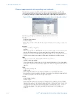
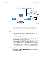
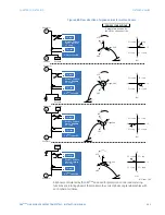
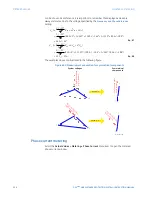
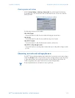
same IRIG-B signal: either the same GPS receiver or IRIG-B generator. Otherwise, the
setpoints of the test set and the phasor measurement unit measurements should not be
compared as they are referenced to different time scales.
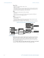
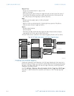
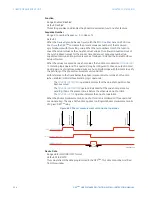
Figure 484: Testing synchrophasor measurement accuracy
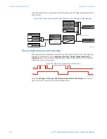
Collecting synchronized measurements
ad hoc
The phasor measurement unit one-shot feature can be used for
ad hoc
collection of
synchronized measurements in the network. Two or more phasor measurement units can
be pre-scheduled to freeze their measurements at the same time. When frozen the
measurements could be collected using EnerVista UR
Plus
Setup or a protocol client.
Data logger
The data logger samples and records up to 16 analog parameters at a user-defined
sampling rate. This recorded data may be downloaded to the EnerVista UR
Plus
Setup software and displayed with parameters on the vertical axis and time on the
horizontal axis. All data is stored in non-volatile memory, meaning that the information is
retained when power to the relay is lost.
For a fixed sampling rate, the data logger can be configured with a few channels over a
long period or a larger number of channels for a shorter period. The relay automatically
partitions the available memory for the channels in use.
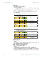
Between the recording intervals, the data logger calculates the maximum, minimum, and
the average value of each channel. At the end of the interval either the maximum,
minimum, or average value is written to the data logger depending on the mode setting.
This ensures that data is not missed if a low rate setting is selected.
In addition, the maximum value, timestamp of maximum, minimum value, time stamp of
minimum are calculated for the channel for the duration of recording since the start of
recording. A high, low, high-high, and low-low alarm can be configured for each channel.
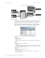
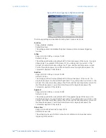
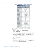
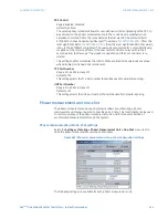
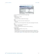
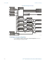
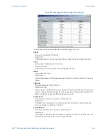
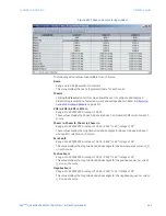
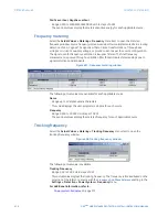
Data logger function configuration
Select the
Settings > Metering > Data Logger > Function
menu item to open the data
logger configuration window.
$&'5
7HVWVHW
3KDVRU
PHDVXUHPHQW
XQLW
'LJLWDO
VFRSH
&KDQQHO
7ULJJHU
&KDQQHO
9ROWDJHFXUUHQWRXW
&KDQQHO
&KDQQHO
7ULJJHU
W
W
I
5(3
,5,*%LQ
,5,*%
VRXUFH
9ROWDJHFXUUHQWLQ
,5,*%LQ
Содержание D90 Plus
Страница 10: ...x D90PLUS LINE DISTANCE PROTECTION SYSTEM INSTRUCTION MANUAL TABLE OF CONTENTS ...
Страница 438: ...428 D90PLUS LINE DISTANCE PROTECTION SYSTEM INSTRUCTION MANUAL PROTECTION FLEXANALOG PARAMETERS CHAPTER 7 PROTECTION ...
Страница 502: ...492 D90PLUS LINE DISTANCE PROTECTION SYSTEM INSTRUCTION MANUAL AUTOMATION FLEXANALOG PARAMETERS CHAPTER 8 AUTOMATION ...
Страница 626: ...616 D90PLUS LINE DISTANCE PROTECTION SYSTEM INSTRUCTION MANUAL ENERVISTA SECURITY MANAGEMENT SYSTEM CHAPTER 13 SECURITY ...
Страница 678: ...668 D90PLUS LINE DISTANCE PROTECTION SYSTEM INSTRUCTION MANUAL SINGLE POLE TRIPPING CHAPTER 15 THEORY OF OPERATION ...
Страница 684: ...674 D90PLUS LINE DISTANCE PROTECTION SYSTEM INSTRUCTION MANUAL DISPOSAL CHAPTER 16 MAINTENANCE ...
Страница 686: ...676 D90PLUS LINE DISTANCE PROTECTION SYSTEM INSTRUCTION MANUAL REVISION HISTORY CHAPTER 17 APPENDIX ...