CHAPTER 7: PROTECTION
CONTROL ELEMENTS
D90
PLUS
LINE DISTANCE PROTECTION SYSTEM – INSTRUCTION MANUAL
293
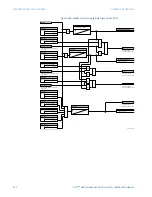
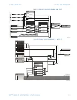
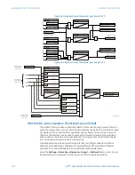
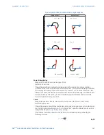
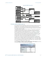
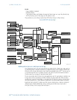
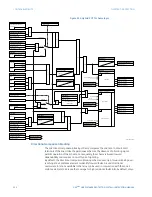
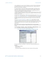
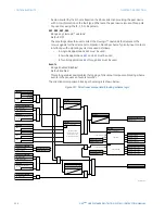
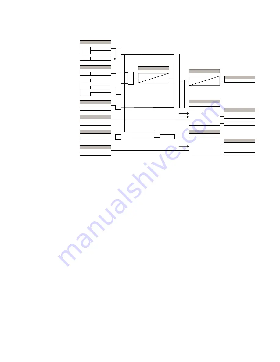
Figure 251: PUTT scheme logic
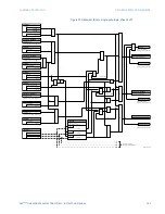
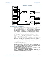
Permissive over-reaching transfer trip
The permissive over-reaching transfer trip (POTT) scheme is intended for two-terminal line
applications only. This scheme uses an over-reaching zone 2 distance element to
essentially compare the direction to a fault at both terminals of the line. Ground directional
overcurrent functions available in the relay can be used in conjunction with the zone 2
distance element to key the scheme and initiate its operation. This provides increased
coverage for high-resistance faults.
For proper operation, the zone 2 phase and ground distance elements must be enabled
and configured as per the principles of distance relaying. The line pickup element should
also be properly enabled and configured to detect line-end-open or weak-infeed
conditions. If used by this scheme, the selected ground directional overcurrent functions
must be enabled and configured accordingly.
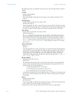
In single-pole tripping applications, the scheme uses local fault type identification provided
by the Phase Selector together with information received from the remote terminal. The
scheme generates output operands (
POTT TX1
through
POTT TX4
) that are used to transmit
the signal to the remote end. Choices of communications channel include remote inputs,
remote outputs, and telecommunications interfaces. When used with telecommunications
facilities the output operands should be assigned to operate output contacts connected to
assert the individual bits at the interface.
To make the scheme fully operational as a stand-alone feature, the output operands must
be configured to interface with other relay functions, in particular the output contacts. The
output operands are typically programmed to initiate a trip, breaker fail, and autoreclose,
and drive an annunciator indication as per user requirements.
When used in conjunction with the trip output element, the POTT scheme is pre-configured
to initiate trip, breaker fail, and single-pole autoreclose actions.
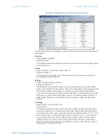
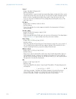
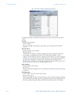
Select the
Settings > Protection > Control > Pilot Schemes > POTT Scheme
menu item to
access the permissive over-reaching transfer trip settings.
$&'5
$1'
$1'
$1'
6(77,1*
(QDEOHG
'LVDEOHG
)XQFWLRQ
2II
%ORFN
6(77,1*6
2II
5;
2II
5;
2II
5;
2II
5;
25
)/(;/2*,&23(5$1'6
3+',67=3.3
*1'',67=3.3
25
25
)/(;/2*,&23(5$1'6
3+',67=3.3
*1'',67=3.3
)/(;/2*,&23(5$1'6
$5)25&(375,3
23(132/(23
6(77,1*
3LFNXS'HOD\
7
SLFNXS
6(77,1*
6HDO,Q'HOD\
7
UHVHW
3KDVHVHOHFWRU
5;
6(77,1*
&RPPXQLFDWLRQ%LWV
581
7ULSWDEOH
)/(;/2*,&23(5$1'
387723
)/(;/2*,&23(5$1'6
387775,3$
387775,3%
387775,3&
387775,33
)/(;/2*,&23(5$1'6
$5)25&(375,3
23(132/(23
$1'
3KDVHVHOHFWRU
6(77,1*
&RPPXQLFDWLRQ%LWV
581
7UDQVPLWWDEOH
)/(;/2*,&23(5$1'6
38777;
38777;
38777;
38777;
Содержание D90 Plus
Страница 10: ...x D90PLUS LINE DISTANCE PROTECTION SYSTEM INSTRUCTION MANUAL TABLE OF CONTENTS ...
Страница 438: ...428 D90PLUS LINE DISTANCE PROTECTION SYSTEM INSTRUCTION MANUAL PROTECTION FLEXANALOG PARAMETERS CHAPTER 7 PROTECTION ...
Страница 502: ...492 D90PLUS LINE DISTANCE PROTECTION SYSTEM INSTRUCTION MANUAL AUTOMATION FLEXANALOG PARAMETERS CHAPTER 8 AUTOMATION ...
Страница 626: ...616 D90PLUS LINE DISTANCE PROTECTION SYSTEM INSTRUCTION MANUAL ENERVISTA SECURITY MANAGEMENT SYSTEM CHAPTER 13 SECURITY ...
Страница 678: ...668 D90PLUS LINE DISTANCE PROTECTION SYSTEM INSTRUCTION MANUAL SINGLE POLE TRIPPING CHAPTER 15 THEORY OF OPERATION ...
Страница 684: ...674 D90PLUS LINE DISTANCE PROTECTION SYSTEM INSTRUCTION MANUAL DISPOSAL CHAPTER 16 MAINTENANCE ...
Страница 686: ...676 D90PLUS LINE DISTANCE PROTECTION SYSTEM INSTRUCTION MANUAL REVISION HISTORY CHAPTER 17 APPENDIX ...

