


536
D90
PLUS
LINE DISTANCE PROTECTION SYSTEM – INSTRUCTION MANUAL
PHASOR MEASUREMENT UNIT
CHAPTER 11: METERING
setting values are effectively added to the measured angles. Therefore, enter a positive
correction of the secondary signal lags the true signal; and negative value if the
secondary signal leads the true signal.
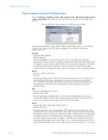
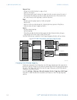
Ia Angle, Ib Angle, Ic Angle, Ig Angle
Range: –5.00 to 5.00° in steps of 0.05
Default: 0.00°
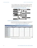
These settings recognize applications with protection class voltage and current sources,
and allow the user to calibrate each channel (ground current and phase A, B, and C
currents) individually to offset errors introduced by VTs, CTs, and cabling. The setting
values are effectively added to the measured angles. Therefore, enter a positive
correction of the secondary signal lags the true signal; and negative value if the
secondary signal leads the true signal.
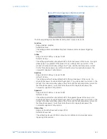
Sequence Voltage Shift Angle
Range: –180 to 180° in steps of 30
Default: 0°
This setting allows correcting positive and negative-sequence voltages for vector groups
of power transformers located between the phasor measurement unit voltage point and
the reference node. This angle is effectively added to the positive-sequence voltage
angle, and subtracted from the negative-sequence voltage angle. Please note the
following.
–
When this setting value is not “0°”, the phase and sequence voltages will not
agree. Unlike sequence voltages, the phase voltages cannot be corrected in a
general case, and therefore are reported as measured.
–
When receiving synchrophasor date at multiple locations, with possibly different
reference nodes, it may be more beneficial to allow the central locations to
perform the compensation of sequence voltages.
–
This setting applies to phasor measurement unit data only. The D90
Plus
calculates
symmetrical voltages independently for protection and control purposes without
applying this correction.
–
When connected to line-to-line voltages, the phasor measurement unit
calculates symmetrical voltages with the reference to the AG voltage, and not to
the physically connected AB voltage.
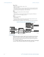
Sequence Current Shift Angle
Range: –180 to 180° in steps of 30
Default: 0°
This setting allows correcting positive and negative-sequence currents for vector groups
of power transformers located between the phasor measurement unit current point and
the reference node. The setting has the same meaning for currents as the
Sequence
Voltage Shift Angle
setting has for voltages. Normally, the two correcting angles are set
identically, except rare applications when the voltage and current measuring points are
located at different windings of a power transformer.
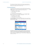
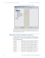
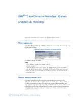
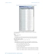
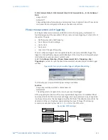
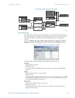
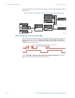
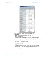
Phasor measurement unit communications
Select the
Settings > Metering > Phasor Measurement Unit > Communication > Comm
Port
menu item to open the phasor measurement unit communications window for port 1.
Содержание D90 Plus
Страница 10: ...x D90PLUS LINE DISTANCE PROTECTION SYSTEM INSTRUCTION MANUAL TABLE OF CONTENTS ...
Страница 438: ...428 D90PLUS LINE DISTANCE PROTECTION SYSTEM INSTRUCTION MANUAL PROTECTION FLEXANALOG PARAMETERS CHAPTER 7 PROTECTION ...
Страница 502: ...492 D90PLUS LINE DISTANCE PROTECTION SYSTEM INSTRUCTION MANUAL AUTOMATION FLEXANALOG PARAMETERS CHAPTER 8 AUTOMATION ...
Страница 626: ...616 D90PLUS LINE DISTANCE PROTECTION SYSTEM INSTRUCTION MANUAL ENERVISTA SECURITY MANAGEMENT SYSTEM CHAPTER 13 SECURITY ...
Страница 678: ...668 D90PLUS LINE DISTANCE PROTECTION SYSTEM INSTRUCTION MANUAL SINGLE POLE TRIPPING CHAPTER 15 THEORY OF OPERATION ...
Страница 684: ...674 D90PLUS LINE DISTANCE PROTECTION SYSTEM INSTRUCTION MANUAL DISPOSAL CHAPTER 16 MAINTENANCE ...
Страница 686: ...676 D90PLUS LINE DISTANCE PROTECTION SYSTEM INSTRUCTION MANUAL REVISION HISTORY CHAPTER 17 APPENDIX ...