background image


Page 1-6 

GMX 200 Installation Manual 

Revision D 

190-00607-04 

1.7 Database 

Updates 

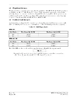
The GMX 200 utilizes a database stored on an SD Memory datacard for easy updating and replacement. 

The database is updated by simply inserting an updated database card into the slot in the front panel in the 

GMX 200. Only Garmin approved datacards may be used in the GMX 200. 
The database on the GMX 200 database card is generated from current Jeppesen-Sanderson data and 

converted to a format that is used by the GMX 200. The data conversion process is performed using 

software that is developed and maintained under Garmin AT configuration management according to 

RTCA/DO-200A, Standards for Processing Aeronautical Data. 
GMX 200 users update their database card by purchasing database subscription updates from Jeppesen-

Sanderson. The database card is programmed using a SD memory card R/W and Jeppesen-provided 

software. Contact Jeppesen at 800-621-5377 or www.jeppesen.com for more information and 

instructions.  
A separate SD memory card reader/writer (R/W) is required to update the database card using a PC. 

Contact Garmin for information on databases available for the GMX 200.  

1.8 Warranty Statement 

Limited Warranty 

This Garmin product is warranted to be free from defects in materials or workmanship for two years from 

the date of purchase.  Within this period, Garmin will at its sole option, repair or replace any components 

that fail in normal use.  Such repairs or replacement will be made at no charge to the customer for parts or 

labor, provided that the customer shall be responsible for any transportation cost.  This warranty does not 

cover failures due to abuse, misuse, accident or unauthorized alteration or repairs. 

THE WARRANTIES AND REMEDIES CONTAINED HEREIN ARE EXCLUSIVE AND IN LIEU OF 

ALL OTHER WARRANTIES EXPRESS OR IMPLIED OR STATUTORY, INCLUDING ANY 

LIABILITY ARISING UNDER ANY WARRANTY OF MERCHANTABILITY OR FITNESS FOR A 

PARTICULAR PURPOSE, STATUTORY OR OTHERWISE.  THIS WARRANTY GIVES YOU 

SPECIFIC LEGAL RIGHTS, WHICH MAY VARY FROM STATE TO STATE. 

IN NO EVENT SHALL GARMIN BE LIABLE FOR ANY INCIDENTAL, SPECIAL, INDIRECT OR 

CONSEQUENTIAL DAMAGES, WHETHER RESULTING FROM THE USE, MISUSE, OR 

INABILITY TO USE THIS PRODUCT OR FROM DEFECTS IN THE PRODUCT.  Some states do not 

allow the exclusion of incidental or consequential damages, so the above limitations may not apply to 

you. 

Garmin retains the exclusive right to repair or replace the unit or software or offer a full refund of the 

purchase price at its sole discretion.  SUCH REMEDY SHALL BE YOUR SOLE AND EXCLUSIVE 

REMEDY FOR ANY BREACH OF WARRANTY. 

To obtain warranty service, contact your local Garmin Authorized Service Center.  For assistance in 

locating a Service Center near you, call Garmin Customer Service at one of the numbers shown below. 

Products sold through online auctions are not eligible for rebates or other special offers from Garmin. 

Online auction confirmations are not accepted for warranty verification. To obtain warranty service, an 

original or copy of the sales receipt from the original retailer is required. Garmin will not replace missing 

components from any package purchased through an online auction. 

Garmin International, Inc. 

Garmin (Europe) Ltd. 

1200 East 151

st

 Street 

Unit 5, The Quadrangle, Abbey Park Industrial Estate 

Olathe, Kansas 66062, U.S.A. 

Romsey, SO51 9DL, U.K. 

Phone: 913/397.8200 

Phone: 44/0870.851241 

FAX: 913/397.8282 

FAX: 44/0870.851251 

Содержание GMX 200

Страница 1: ...190 00607 04 March 2007 Revision D GMX 200 Installation Manual ...

Страница 2: ...in International Inc 1200 E 151st Street Olathe KS 66062 USA Telephone 913 397 8200 Aviation Panel Mount Technical Support Line Toll Free 1 888 606 5482 www garmin com Garmin Europe Ltd Unit 5 The Quadrangle Abbey Park Industrial Estate Romsey SO51 9DL U K 44 1794 519944 44 1794 519222 Garmin AT Inc 2345 Turner Rd SE Salem OR 97302 USA Telephone 503 581 8101 RECORD OF REVISIONS Revision Revision D...

Страница 3: ...a s Proposition 65 If you have any questions or would like additional information please refer to our web site at www garmin com prop65 CAUTION The GMX 200 uses a lens coated with a special anti reflective coating that is very sensitive to skin oils waxes and abrasive cleaners CLEANERS CONTAINING AMMONIA WILL HARM THE ANTI REFLECTIVE COATING It is very important to clean the lens using a clean lin...

Страница 4: ...Page ii GMX 200 Installation Manual Revision D 190 00607 04 This Page Intentionally Left Blank ...

Страница 5: ...2 3 3 Materials Required but Not Supplied 2 2 2 4 Installation Considerations 2 2 2 4 1 Minimum System Configuration 2 2 2 4 2 External Sensors 2 2 2 4 3 Mounting Considerations 2 3 2 4 4 Cable and Wiring Considerations 2 3 2 4 5 Air Circulation and Cooling 2 3 2 4 6 Compass Safe Distance 2 3 3 INSTALLATION PROCEDURE 3 1 3 1 Unpacking Unit 3 1 3 2 Special Tools Required 3 1 3 3 Equipment Mounting ...

Страница 6: ...ation of GDL 69 XM Satellite Radio 5 19 5 5 System Operational Checkout 5 19 5 5 1 Software and Database Test 5 19 5 5 2 General Serial Data Source Tests 5 20 5 5 3 GPS Navigation Source Interface Test 5 20 5 5 4 Altitude Source Interface Test 5 21 5 5 5 Stormscope Interface Test 5 22 5 5 6 Traffic System Interface Test 5 23 5 5 7 TAWS System Interface Test 5 25 5 5 8 Weather Radar Interface Check...

Страница 7: ...ription 1 3 Figure 3 1 Shield Block Install onto Backshell Connector Assembly 3 5 Figure 3 2 Shielded Cable Preparation 3 6 Figure 3 3 Configuration Module Installation 3 8 Figure 3 4 Backshell Assembly to Mounting Tube Installation 3 9 Figure D 1 Connector Location D 2 Figure D 2 Cockpit Panel Configuration for a Large Panel D 3 Figure D 3 Cockpit Panel Configuration for a Small Panel D 3 Figure ...

Страница 8: ...rt Numbers 3 2 Table 3 2 Recommended Crimp Tools 3 3 Table 3 3 Backshell Assembly 3 4 Table 3 4 Configuration Module Kit 011 00979 02 3 7 Table 3 5 Configuration Module Wire Color Reference Chart 3 7 Table 3 6 Unit Power Loads 3 10 Table 5 1 Preferred RS 232 RS 422 Data Port Configurations P2001 5 1 Table 5 2 GMX 200 I O Data Port Configurations P2002 5 2 Table 5 3 GMX 200 Series Post Installation...

Страница 9: ...d GMX 200 I O models and references applicable to the GMX 200 I O model only are identified as such Refer to Section 7 Limitations for additional information It is possible for installers to seek evaluation and approval of an alternate installation by means of the field approval process This manual and all the data contained within may be used by the installer in pursuit of a field approval 1 2 In...

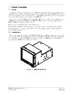
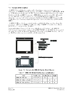
Страница 10: ...on in addition to the information available with the GDL 69 The GMX 200 I O model includes additional interface capabilities that allow connection of a weather radar sensor TAWS sensor ARINC 429 traffic sensor Ryan TCAD RS 232 interface and a Garmin GTX330 Mode S Transponder for TIS traffic Starting with software Version 2 10 SafeTaxi and FliteCharts can be displayed on the GMX 200 SafeTaxi airpor...

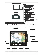
Страница 11: ...GMX 200 Installation Manual Page 1 3 190 00607 04 Revision D Figure 1 3 Example of a GMX 200 I O System Block Diagram Figure 1 4 GMX 200 Front Panel Description ...

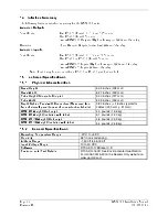
Страница 12: ...5 1 Physical Characteristics Bezel Height 5 04 inches 128 mm Bezel Width 6 27 inches 159 mm Tube Height Dimple to Dimple 5 00 inches 127 mm Tube Width 6 25 inches 159 mm Depth Behind Panel with Connectors Measured from face of aircraft panel to rear of connector backshells 9 82 inches 2 inches typical for cables 250 mm 51 mm GMX 200 Weight Unit only 4 3 pounds 1 96 kg GMX 200 Weight Installed with...

Страница 13: ...mance Standard Software RTCA DO 178B TSO C63c Airborne Weather and Ground Mapping Pulsed Radar RTCA DO 173 Level C TSO C110a Airborne Passive Thunderstorm Equipment RTCA DO 191 Level D TSO C113 Multipurpose Electronic Displays SAE AS 8034 Level C D TSO C118 Traffic Alert and Collision Avoidance System TCAS I RTCA DO 197 Level D TSO C147 Traffic Advisory System TAS Airborne Equipment RTCA DO 197A L...

Страница 14: ...s warranty does not cover failures due to abuse misuse accident or unauthorized alteration or repairs THE WARRANTIES AND REMEDIES CONTAINED HEREIN ARE EXCLUSIVE AND IN LIEU OF ALL OTHER WARRANTIES EXPRESS OR IMPLIED OR STATUTORY INCLUDING ANY LIABILITY ARISING UNDER ANY WARRANTY OF MERCHANTABILITY OR FITNESS FOR A PARTICULAR PURPOSE STATUTORY OR OTHERWISE THIS WARRANTY GIVES YOU SPECIFIC LEGAL RIG...

Страница 15: ...stallation Materials 2 3 1 Configurations Available The GMX 200 is available in eight configurations under the following part numbers Catalog part numbers are shown with and without the installation kit Table 2 1 Configurations Available Model Bezel Color Unit P N Catalog P N Without Installation Kit Catalog P N With Installation Kit GMX 200 Black 011 01271 00 010 00483 00 010 00483 01 GMX 200 Gra...

Страница 16: ...lated steel Flat Washer 8 032 thick 174 ID 375 OD for terminating shield drains to shield block Shield Terminators Silicon Fusion Tape 2 4 Installation Considerations 2 4 1 Minimum System Configuration The minimum GMX 200 installation requires the following items GMX 200 or GMX 200 I O External GPS Navigation sensor NOTE Altitude from GPS Navigation sensor or an altitude encoder is required for th...

Страница 17: ...tion limitations in section 7 2 The preferred location would minimize pilot head movement when transitioning between looking outside of the flight deck and viewing and operating the GMX 200 Reference Figure D 4 A sample diagram of a typical cockpit front panel view of the GMX 200 is shown in Figure D 2 The GMX 200 should be placed as high as possible in the radio stack to minimize the shifting of ...

Страница 18: ...Page 2 4 GMX 200 Installation Manual Revision D 190 00607 04 This Page Intentionally Left Blank ...

Страница 19: ...tack using the sixteen flat head screws specified in Section 2 3 3 The mating holes in the avionics stack must also be countersunk to accept the screw head so that the screw head is flush with the inside surface of the mounting tube or adjoining radios CAUTION Failure to properly countersink the mounting holes will result in damage to the GMX 200 Mounting screw heads must not protrude into the mou...

Страница 20: ... to the rear of the mounting tube Route the wiring bundle as appropriate Avoid sharp bends 3 4 1 Wiring Harness Allow adequate space for installation of cables and connectors The installer supplies and fabricates all of the cables All electrical connections are made through a 37 pin D Subminiature connector and 62 pin D subminiature connector for the GMX 200 I O provided by Garmin Construct the wi...

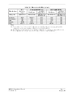
Страница 21: ... Positronic 9507 9502 11 N A N A N A ITT Cannon N A N A N A N A N A AMP N A N A N A N A N A Daniels AFM8 K13 1 N A K41 N A Astro 615717 615724 N A 615722 N A Notes 1 Contacts listed are not to be used for configuration module wiring Use the contacts supplied with the configuration module when installing configuration module wires in P2001 2 Non Garmin part numbers shown are not maintained by Garmi...

Страница 22: ...ams Appendix E As Required 5 5 Shield Terminator As Required 5 6 6 Wire Insulated 20 22 AWG As Required 5 6 7 Socket Contacts 336 00022 00 or 336 00055 00 1 2 8 Ring terminal 8 insulated 18 22 AWG 14 16 AWG MS25036 149 MS25036 153 MS25036 156 5 9 Screw PHP 8 32x 312 Stainless or Cad Plated Steel MS51957 42 MS35206 242 5 10 Split Washer 8 045 compressed thickness Stainless or Cad plated steel MS353...

Страница 23: ...7 04 Revision D 3 4 2 1 Shield Block Assembly Procedure The parts for the connector and backshell assembly for GMX 200 installations are listed in Table 3 3 and shown in Figure 3 1 Figure 3 1 Shield Block Install onto Backshell Connector Assembly ...

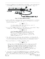
Страница 24: ...d instructions on product use refer to Raychem installation procedure 4 Slide a shield terminator 5 onto the prepared cable assembly 4 and connect the wire 6 to the shield using a heat gun approved for use with solder sleeves The chosen size of solder sleeve must accommodate both the number of conductors present in the cable and the wire 6 to be attached 5 Repeat steps 2 through 4 as needed for th...

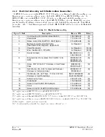
Страница 25: ...3 4 Conductor Harness 325 00122 00 4 Socket Contact Crimp 20 336 00022 01 Table 3 5 Configuration Module Wire Color Reference Chart Color Function P2001 Contact Black Ground 27 Red Vcc 24 Yellow Data 19 White Clock 17 Assemble the configuration module as follows 1 Crimp socket contacts 4 onto each wire of the four conductor wire harness 3 Strip 1 8 of insulation from each wire prior to crimping 2 ...

Страница 26: ...Page 3 8 GMX 200 Installation Manual Revision D 190 00607 04 Figure 3 3 Configuration Module Installation ...

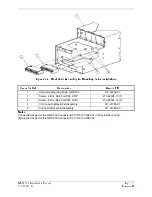
Страница 27: ...y Mounting Tube GMX 200 115 00746 00 2 Screw 4 40 x 365 FLHP82 SS P 211 62234 10 1 3 Screw 4 40 x 365 FLHP82 SS P 211 62234 10 2 4 I O Connector Backshell Assembly 011 01283 01 5 Connector Backshell Assembly 011 01283 00 Notes 1 Supplied as part of the GMX 200 Connector Kit P N 011 01283 01 I O Installations Only 2 Supplied as part of the GMX 200 Connector Kit P N 011 01283 00 ...

Страница 28: ...r the GMX 200 and GMX 200 I O 3 6 Electrical Load Analysis An electrical load analysis should be completed on each aircraft prior to installation in accordance with AC 43 13 1B Chapter 11 and recorded on FAA Form 337 Use the following values for computation Table 3 6 Unit Power Loads GMX 200 Unit Status Max Current 28 VDC Max Current 14 VDC Off 014 A 023 A On 1 16 A 2 24 A GMX 200 I O Unit Status ...

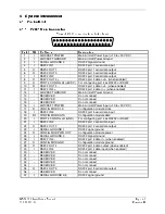
Страница 29: ... connect 14 RESERVED Do not connect 15 RESERVED Do not connect 16 I AIRCRAFT POWER Main Aircraft Power Input 10 to 30 VDC 17 O CONFIG MOD CLK Configuration module clock 18 I RS232 IN 5 RS232 port 5 serial data input 19 I O CONFIG MOD DATA Configuration module data 20 I PORT 4 CONFIG LO GND For configuring port 4 as RS232 or RS422 21 I RS232 IN 2 RS232 port 2 serial data input 22 O RS232 OUT 2 RS23...

Страница 30: ... Output 1B TAWS 18 O 429 OUT 1A ARINC 429 Output 1A TAWS 19 I 453 708 IN 1B ARINC 453 708 Input 1B Weather Radar 20 I RESERVED Do not connect 21 I 453 708 IN 2A ARINC 453 708 Input 2A TAWS 22 RESERVED Do not connect 23 RESERVED Do not connect 24 RESERVED Do not connect 25 RESERVED Do not connect 26 RESERVED Do not connect 27 RESERVED Do not connect 28 RESERVED Do not connect 29 RESERVED Do not con...

Страница 31: ...4 2 1 Power The GMX 200 will accept input power from 9 to 33 VDC Both sets of power inputs must be connected in the installation P2001 1 Aircraft Power P2001 16 Aircraft Power P2001 2 Power Ground P2001 12 Power Ground Refer to Appendix E for recommended power connections 4 2 2 Configuration Module The GMX 200 stores installation specific configuration information in an aircraft configuration modu...

Страница 32: ...rial Ground 4 5 P2001 7 RS232 In 3 P2001 9 Port 4 Config Hi 5VDC P2001 6 RS232 Out 3 P2001 20 Port 4 Config Lo GND P2001 25 Serial Ground 3 P2001 11 RS422 In 4 P2001 26 RS422 In 4 P2001 8 RS422 Out 4 P2001 10 RS422 Out 4 4 2 3 2 ARINC 429 GMX 200 I O only The GMX 200 I O provides two ARINC 429 inputs and two ARINC 429 outputs The configuration of these ARINC 429 channels is done automatically when...

Страница 33: ... receive weather and terrain data from suitable weather radar and TAWS systems Refer to section 5 1 1 for information on configuring the data sources 4 2 4 Discrete Outputs GMX 200 I O only The GMX 200 I O provides three discrete outputs The configuration of these inputs is done automatically when data sources are selected during system configuration P2002 5 Discrete Out 1 Weather Radar P2002 7 Di...

Страница 34: ...Page 4 6 GMX 200 Installation Manual Revision D 190 00607 04 This Page Intentionally Left Blank ...

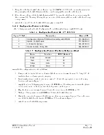
Страница 35: ... NOTE Only one FIS source may be connected to the GMX 200 or GMX 200 I O at one time Table 5 1 Preferred RS 232 RS 422 Data Port Configurations P2001 GMX 200 and GMX 200 I O PORT 1 RS 232 GNS 430 480 530 or equivalent 1 PORT 2 RS 232 Altitude encoder or option 1 2 3 PORT 3 RS 232 SL30 GDL 69 or option 4 PORT 4 RS 232 or RS 422 GDL90 WX 500 PORT 5 RS 232 Ryan TCAD or option 5 1 GPS altitude e g fro...

Страница 36: ...urations P2002 GMX 200 I O Only Port Type Description ARINC 453 708 In 1 ARINC 453 Weather Radar Display ARINC 429 Out 2 ARINC 429 Weather Radar Control Discrete Out 1 Active Low Discrete Weather Radar Power ARINC 429 In 1 ARINC 429 Traffic Display Discrete Out 2 and 3 Active Low Discrete TAS Mode Control RS 232 Port 1 2 3 4 or 5 1 RS 232 Ryan TCAD Traffic ARINC 453 708 In 2 ARINC 453 Terrain Disp...

Страница 37: ...ther keys where 1 is the top line select key 4 is the fourth key down and 6 is the lower most line select key If other keys are pressed before or during this sequence the GMX 200 will be in the normal operational mode To enter the install mode turn off the GMX 200 and start again at step 1 3 Press the FN key until the INSTL function is present If the INSTL function is not found restart the unit Ca...

Страница 38: ...an be made using the line select key beside the appropriate function to toggle between Enabled and Disabled Record all of the settings in the checkout log sheet provided in Table 5 3 1 If not already on the Function menu press the FUNC smart key to bring up the Enable Disable Functions menu Enable or disable functions as required a Message Enable to allow viewing of system messages b Custom Map En...

Страница 39: ...on NOTE The Flight Plan function must be enabled to conduct the system operational checkout c Terrain Enable only if an altitude source is supplied to the GMX 200 GPS or pressure or if a suitable TAWS sensor is installed d FIS Data Link Enable only if a GDL 90 UAT or GDL 69 69A system is installed e XM Sat Radio Enable only if a GDL 69A i e with weather and audio is installed This should be disabl...

Страница 40: ...ng Enable only if WX 500 is installed b Radar Enable only if a unit is an I O model and interfaced to a radar unit c System Enable the function to allow viewing of the System function NOTE The System function must be enabled to conduct the system operational checkout 4 Press the Main Menu line select key to return to the first menu page ...

Страница 41: ...B Select the type of GPS source that is connected Refer to Section C 1 c Altitude Source Selections None Port 1 Port 2 Port 3 Port 4 Port 5 Select the port to which an external altitude source is connected Select None if the GMX 200 does not use any altitude If the altitude data is supplied from the external GPS the Altitude Source must be set to the same port that the external GPS is connected to...

Страница 42: ...e Port 1 Port 2 Port 3 Port 4 Port 5 Select the port to which a Ryan TCAD is connected d Traffic Source 429 Selections None TAS TAS Disp Select the port to which an ARINC 429 traffic source is connected If the GMX 200 is wired to drive the traffic system discrete inputs and control the traffic system select the TAS option If the GMX 200 is not wired to drive the discrete inputs e g when an additio...

Страница 43: ...Select source only if a radar sensor is installed Select the ART 2000 option if the unit is wired to an ART 2100 b TAWS Source Selections None TAWS8000 KGP 560 Select a source only if a TAWS sensor is installed c GDL69 Source Selections None Port 1 Port 2 Port 3 Port 4 Port 5 Select the port to which a GDL 69 or GDL 69A is connected 4 Press the Main Menu line select key to return to the first menu...

Страница 44: ...t ID Use the smart keys to enter edit up to 8 characters and press the MENU ENTER key when done b Ownship Symbol Selections Single Engine Twin Engine Jet Helicopter Select the type of ownship symbol to be displayed on the map pages c Terrain Clearance Mode Selections Normal Special Set to Normal for all operations d Demo Mode Not for Flight Selections Disabled Enabled Select Disabled for all aircr...

Страница 45: ...ponder the GDL 90 Code Edit option must be set to Disabled It is recommended that this always be set to Disabled c GDL 69 Cable Loss only required if GDL 69 69A system is installed Selections 0 to 50 dB in 0 1 dB increments Press the line select key for this option to allow editing of the cable loss value Use the smart keys to change the cable loss value and press the MENU ENTER key when done Refe...

Страница 46: ...the database SD card from the front SD card slot and insert a ChartView Activation Card P N 010 00489 50 3 Turn the GMX 200 on the GMX 200 will begin activating the ChartView feature 4 Wait for the message ChartView Feature Unlocked Please restart unit to appear Turn off the GMX 200 remove the activation card and insert the database card that was previously removed 5 Turn on the GMX 200 and wait f...

Страница 47: ... taken by personnel when operating airborne weather radar on the ground 5 4 1 1 ART 2000 Calibration Procedures Using GMX 200 Refer to the Bendix King ART2000 Color Weather Radar System Installation Manual Revision 4 or later Follow the instructions in Stabilization calibration with Radar Indicator or its equivalent Skip the description in the ART2000 manual on how to enter calibration mode The GM...

Страница 48: ...ounted on a tilt table for proper calibration Analog stabilization values for pitch and roll can only be adjusted if the GWX 68 is provided with a 400 Hz reference input The GMX 200 must be in the Install mode to calibrate the radar head Follow the instructions below 1 Turn the GMX 200 on 2 After boot up is complete key in the install sequence 1 4 6 on the line select keys to enter the Install mod...

Страница 49: ...LT SETTING between 5 DOWN and 10 DOWN decreases the PITCH ANGLE field Use the TILT keys to set the PITCH ANGLE field to 0 0 1 0 Upon reaching the desired PITCH ANGLE setting quickly set the TILT SETTING to between 5 UP and 5 DOWN to lock in the PITCH ANGLE setting 5 4 1 2 4 Roll Offset 1 Check that the tilt table is set for 0 roll 2 Use the GAIN and GAIN keys to set the GAIN to between 14 and 16 T...

Страница 50: ...ion 5 4 1 2 7 Save Configuration 1 Use the GAIN and GAIN keys to set the GAIN to between 3 5and 5 5 The AZIMUTH ANGLE field should also display 08 2 Set the TILT SETTING to 15 0D The fault fields will flash on indicating the save procedure is beginning If the save procedure is successful the GYRO fault will disappear 3 If the GYRO remains unchanged adjust the TILT SETTING to 0 and repeat step 2 5 ...

Страница 51: ... the FN key until one of the smart key options is RADAR If the RADAR option is not available ensure that the GMX 200 is configured for a radar source 4 Press the smart key corresponding to the RADAR option You will now switch to the Radar page 5 Press the STBY ON line select key on the GMX 200 to put the radar unit into standby mode This may take up to twenty seconds 6 Once the radar is in standby...

Страница 52: ... 4 Press the smart key corresponding to the RADAR option You will now switch to the Radar page 5 Press the STBY ON line select key on the GMX 200 to put the radar unit into standby mode This may take up to twenty seconds 6 Once the radar is in standby mode one of the menu options will be TEST Press the TEST key 7 Once the GMX 200 is in Test mode press the MENU ENT key to switch to the Setup page 8...

Страница 53: ... NOTE Throughout the checkout section references are made to particular GMX 200 functions If the function is not available ensure that the GMX 200 has been configured correctly as described in Section 5 3 5 5 1 Software and Database Test 1 Turn on power to the GMX 200 2 Verify all self tests pass on the main startup screen 3 Verify the expiration on the Jeppeson NavData Database 4 If activated ver...

Страница 54: ...d as invalid 4 Before proceeding ensure that all of the serial data is valid by looking at the corresponding entry in the Valid column YES indicates data is valid NO indicates data is not valid and indicates that the port is not configured 5 5 3 GPS Navigation Source Interface Test The GMX 200 can receive position and flight plan data from an external GPS Navigation source If a GNS 480 is used as ...

Страница 55: ...200 can receive altitude data from a GPS Navigation sensor pressure or GPS altitude or an altitude encoder pressure altitude This check verifies that the GMX 200 is configured correctly and is receiving altitude data NOTE If the GMX 200 is configured for an external TAWS Source altitude will not be displayed 5 5 4 1 GPS Altitude Source 1 Ensure that the GPS Navigation Source has acquired a positio...

Страница 56: ...a from an L3 Communications WX 500 Stormscope sensor This check verifies that the GMX 200 is configured correctly and is receiving and transmitting data to the Stormscope 1 Verify that the amber LT flag is not displayed 2 Select the Lightning LT function on the GMX 200 3 Verify that you are able to control the mode of the Stormscope using the GMX 200 NOTE The four standard Stormscope test screens ...

Страница 57: ... above the Vert display verify that the status of the traffic system is either TAS Standby or blank i e no status should be presented NOTE If the GMX 200 is configured for TAS Disp i e a display other than the GMX 200 is controlling the traffic system then the following steps do not have to be carried out 4 Press the MENU ENT key and press the STANDBY OPERATE line select key to change the mode of ...

Страница 58: ... displayed by pressing the MENU ENT key change the altitude display mode from Relative to Absolute Verify that the altitude data tags for displayed traffic remain valid and are not if the altitude data tags dash out when Absolute is selected verify that the altitude source is providing valid data to the GMX 200 5 5 6 3 Garmin GTX 33 330 Interface Test If a Garmin GTX 33 330 sensor has been connect...

Страница 59: ...ark TAWS 8000 or Honeywell Bendix King KGP 560 860 TAWS KMH 820 IHAS system has been connected to the GMX 200 I O the interface should be verified as described in this section 1 Verify that the amber TAWS flag is not displayed 2 Select the Terrain TER function on the GMX 200 3 From the TAWS control panel execute a self test Verify that the GMX 200 displays the TAWS generated test pattern and the T...

Страница 60: ...ress the HORIZ VERT line select key Verify that the antenna scan changes from the horizontal scan to the vertical scan and the display changes to a vertical scan with the test pattern displayed 5 5 9 Garmin GDL 69 69A Checkout Procedure If a Garmin GDL 69 has been connected to the GMX 200 I O the interface should be verified as described section 5 5 9 1 If a Garmin GDL 69A has been connected to th...

Страница 61: ...played 2 Select the Flight Information Service FIS function on the GMX 200 and then press the fourth rightmost smart key repeatedly until the status page is displayed 3 Press the MENU ENT key to display the menu items and press the Products line select key followed by the Diagnostics line select key to get to the activation page 4 Verify that the Data Radio ID field has a valid value and does not ...

Страница 62: ... headsets Adjustment of the volume may be required 5 5 10 Garmin GDL 90 Checkout Procedure If a Garmin GDL 90 has been connected to the GMX 200 the interface should be verified as described in this section 1 Verify that the amber TRAF flag is not displayed 2 Select the Traffic TRAF function on the GMX 200 3 On the lower right hand corner of the traffic function page verify that a valid Broadcast I...

Страница 63: ... systems interfaced to the GMX 200 will cause the associated system flags on the GMX 200 to be displayed This is normal behavior and does not constitute a test failure 4 Apply power to the other avionics systems one at a time and verify that the system is functioning properly without any unacceptable interference caused by the GMX 200 Ensure that there is no unacceptable interference in the GMX 20...

Страница 64: ...Page 5 30 GMX 200 Installation Manual Revision D 190 00607 04 This Page Intentionally Left Blank ...

Страница 65: ...led NAV Source None Port ____ Traffic Enabled Disabled Lightning Source None Port ____ Flight Plan Enabled Disabled UAT Source None Port ____ Terrain Enabled Disabled Ryan TCAD Source None Port ____ FIS Data Link Enabled Disabled Traffic Source 429 None TAS TAS Disp XM Sat Radio Enabled Disabled Transponder TIS Source None GTX 330 Lightning Enabled Disabled Radar Source None ________________ Radar...

Страница 66: ...n NavData current N A Traffic System Interface checked N A Electronic Charts current N A TAWS System Interface checked General Serial Data Sources checked N A Weather Radar Interface checked GPS Source Interface checked N A GDL 69 69A Interface checked N A Altitude Source Interface checked N A GDL 90 Interface checked N A Stormscope Interface checked EMI RFI Check Pass Fail COMMENTS Page 2 of 2 ...

Страница 67: ...n module with a known good module INSTL function not shown in install mode Improper key sequence entered Ensure that the proper installation key sequence is carefully entered after the power on self test is complete Too many keys pressed in key sequence Ensure that no other keys are pressed prior to entering the sequence Cycle through functions not completed Cycle through the available functions b...

Страница 68: ...S as source for altitude data and GPS altitude The GPS source does not provide GPS altitude Verify in Appendix C that GPS source can supply selected altitude type GMX 200 is configured to use a GX unit as source for altitude data and GX not configured properly Verify that GX has extended data output enabled Wiring error If a separate altitude encoder is used ensure that the wiring between the GMX ...

Страница 69: ...in the INSTL pages Unit shows LINK data flag Data port configuration incorrect Ensure that the data port is configured correctly for the GDL 69 data link and the selected port matches how the GMX 200 is wired for the GDL 69 69A data link GDL 69 69A data link not powered up not functioning properly Ensure that the GDL 69 69A data link has power applied and is functional Wiring error Ensure that the...

Страница 70: ...er radar is on and broadcasting energy No action required Unit shows RDR Flashing Green This is not a problem This is an indication that the weather radar is in the Hold mode and broadcasting energy No action required 6 2 Contacting the Factory for Assistance If the GMX 200 fails to operate despite troubleshooting efforts contact Customer Service for assistance GARMIN International Inc 1200 East 1...

Страница 71: ... 200 Such modifications are beyond the scope of this STC In order to provide optimal display view ability and limit any color shift the GMX 200 must be installed at a height in the panel so that the pilot s eye will not exceed the 30 downward view to the display as illustrated in Figure D 4 For preservation of essential equipment in aircraft with multiple power busses the GMX 200 should be powered...

Страница 72: ...Page 7 2 GMX 200 Installation Manual Revision D 190 00607 04 This Page Intentionally Left Blank ...

Страница 73: ...e surface of the display The GMX 200 uses a lens coated with a special anti reflective coating that is very sensitive to skin oils waxes and abrasive cleaners 8 3 Altitude Encoder Pressure altitude may be used for the GMX 200 terrain awareness function If the GMX 200 is installed in conjunction with an altitude encoder it is recommended that the encoder be calibrated every 24 months Refer to the m...

Страница 74: ...Page 8 2 GMX 200 Installation Manual Revision D 190 00607 04 This Page Intentionally Left Blank ...

Страница 75: ...purpose of installation and approval of installation of the GMX 200 and associated interfaces to other previously approved equipment A 3 Continued Airworthiness Instructions Refer to the GMX 200 Instructions for Continued Airworthiness Garmin P N 190 00607 00 which is available on the Garmin web site at www garmin com Download from the Dealers Only page A 4 STC Approved Model List The GMX 200 STC ...

Страница 76: ...Page A 2 GMX 200 Installation Manual Revision D 190 00607 04 This Page Intentionally Left Blank ...

Страница 77: ...lation Manual Page B 1 190 00607 04 Revision D Appendix B ENVIRONMENT QUALIFICATION FORM Go to the Dealers Only site at http www garmin com for the latest Environmental Qualification Form Document number 005 00315 33 ...

Страница 78: ...Page B 2 GMX 200 Installation Manual Revision D 190 00607 04 This Page Intentionally Left Blank ...

Страница 79: ...The following NAV sources are compatible with the GMX 200 Manufacturer Model Data Format Notes Garmin SL30 RS 232 Garmin GNS 480 CNX80 RS 232 Data is provided over MapMX interface a separate serial interface is not required C 3 Altitude Source The following Altitude sources are compatible with the GMX 200 Manufacturer Model Data Format Notes Garmin SL70 70R RS 232 Pressure altitude Garmin GNS 480 ...

Страница 80: ... The following weather sources are compatible with the GMX 200 Manufacturer Model Data Format Notes Allied Signal RS 181A King P N 071 1315 00 Bendix King P N 3614077 8101 ARINC708 GMX 200 I O Radar TAWS and Traffic Radar Models only RS 181 VP model with vertical scan is not currently supported Bendix King ART2000 Mod 3 or Higher Bendix King P N 071 01519 0101 ARINC708 GMX 200 I O Radar TAWS and T...

Страница 81: ...ware is required Honeywell KGP 860 ARINC708 003 or later software is required L3 Goodrich Landmark TAWS 8000 ARINC708 C 7 Data Link The following data link is compatible with the GMX 200 When a GDL 69 69A and GDL 90 are installed the GMX 200 will process the FIS data from the GDL 69 69A and traffic data from the GDL 90 ignoring the FIS data from the GDL 90 Manufacturer Model Data Format Notes Garm...

Страница 82: ...Page C 4 GMX 200 Installation Manual Revision D 190 00607 04 This Page Intentionally Left Blank ...

Страница 83: ...00 D 2 Diagram List Figure D 1 Connector Location Figure D 2 Cockpit Panel Configuration for a Large Panel Figure D 3 Cockpit Panel Configuration for a Small Panel Figure D 4 Maximum Vertical Viewing Angle Side View Figure D 5 Sample GNX 480 and GMX 200 Mounting with GNS 480 Figure D 6 GMX 200 Mounting Tube Assembly Dimensions Figure D 7 GMX 200 and GMX 200 I O Dimensions and Center of Gravity ...

Страница 84: ...Page D 2 GMX 200 Installation Manual Revision D 190 00607 04 I O Connector 62 Pin Connector J2002 Main Connector 37 Pin Connector Figure D 1 Connector Location ...

Страница 85: ...GMX 200 Installation Manual Page D 3 190 00607 04 Revision D Figure D 2 Cockpit Panel Configuration for a Large Panel M X2 0 M FD Figure D 3 Cockpit Panel Configuration for a Small Panel ...

Страница 86: ...Page D 4 GMX 200 Installation Manual Revision D 190 00607 04 Figure D 4 Maximum Vertical Viewing Angle Side View GMX 200 30 maximum Instrument Panel Horizontal ...

Страница 87: ...GMX 200 Installation Manual Page D 5 190 00607 04 Revision D Figure D 5 Sample GNS 480 and GMX 200 Mounting with GNS 480 ...

Страница 88: ...Page D 6 GMX 200 Installation Manual Revision D 190 00607 04 EXHAUST FAN COOLING AIR INTAKE DUCT Figure D 6 GMX 200 Mounting Tube Assembly Dimensions ...

Страница 89: ...GMX 200 Installation Manual Page D 7 190 00607 04 Revision D Figure D 7 GMX 200 and GMX 200 I O Dimensions and Center of Gravity ...

Страница 90: ...Page D 8 GMX 200 Installation Manual Revision D 190 00607 04 This Page Intentionally Left Blank ...

Страница 91: ...figuration information for the GMX 200 and external sensors as appropriate E 2 Diagram List Figure E 1 Power and Configuration Module Figure E 2 GPS Position Source Figure E 3 RS 232 Interfaces Figure E 4 Stormscope Figure E 5 GDL 69 69A Data Link Figure E 6 GDL 90 Data Link Includes Traffic Figure E 7 Traffic Figure E 8 TAWS Figure E 9 Weather Radar Figure E 10 ARINC 453 Wiring for Multiple Radar...

Страница 92: ...Page E 2 GMX 200 Installation Manual Revision D 190 00607 04 This Page Intentionally Left Blank ...

Страница 93: ...T POWER AIRCRAFT POWER AIRCRAFT POWER POWER GROUND POWER GROUND POWER GROUND CONFIG MOD CLK CONFIG MOD CLK CONFIG MOD CLK CONFIG MOD DATA CONFIG MOD DATA CONFIG MOD DATA 19 19 19 24 24 24 CONFIG MOD PWR CONFIG MOD PWR CONFIG MOD PWR 20 AWG 20 AWG 20 AWG 20 AWG 20 AWG 20 AWG 20 AWG 20 AWG 20 AWG 20 AWG 20 AWG 20 AWG BLK BLK BLK WHT WHT WHT YEL YEL YEL RED RED RED AIRCRAFT AIRCRAFT AIRCRAFT GROUND G...

Страница 94: ...T EXTENDED DATA MUST BE ENABLED IF PRESSURE ALTITUDE IS TO BE PROVIDED TO THE GMX 200 THROUGH THE GX SERIES UNIT ENABLED IF PRESSURE ALTITUDE IS TO BE PROVIDED TO THE GMX 200 THROUGH THE GX SERIES UNIT 7 FOR SL SERIES GMX 200 MUST BE CONFIGURED FOR EXTERNAL GPS POSITION SOURCE ON PORT 1 OR WHICHEVER PORT GPS IS 7 FOR SL SERIES GMX 200 MUST BE CONFIGURED FOR EXTERNAL GPS POSITION SOURCE ON PORT 1 O...

Страница 95: ... SHOWN TXD2 SHOWN IN PARENTHESES PIN 4 MUST BE GROUNDED TO SELECT APOLLO SERIAL ALTITUDE FORMAT 7 IF THE SL70 SL70R HAS GRAY CODE ALTITUDE PROVIDED TO IT IT CAN PROVIDE ALTITUDE TO THE GMX 200 THE SL70 SL70R SERIAL PORT CONFIGURATION MUST BE SET TO ALT SOURCE GRAY BAUD 1200 AND TX EXT 8 THE SL30 SERIAL OUTPUT DOES NOT REQUIRE ANY CONFIGURATION DO NOT CONNECT THE SL30 TO THE GMX 200 IF A GNS 480 CN...

Страница 96: ...ON PORT 4 OR WHICHEVER PORT IF PORT 4 IS USEDAS AN RS422 PORT RS232 PORT 4 CANNOT BE USED WX 500 IS CONNECTED TO AND THE LIGHTNING FUNCTION MUST BE ENABLED P2001 GMX200 MFD WX 500 STORMSCOPE 20 5 8 P2 5 6 RS422 IN 4 PORT 4 CONFIG LO 10 8 RS422 TX4 26 11 9 29 RS 422_Rx RS 422_Tx RS422 RX4 P2001 GMX200 MFD WX 500 STORMSCOPE 12 24 13 25 P3 3 4 RS232 IN 4 PORT 4 CONFIG HI RS422 CONNECTION RS232 CONNEC...

Страница 97: ...OUNDS TO AIRCRAFT CHASSIS WITH AS SHORT A CONDUCTOR AS PRACTICAL 3 RS232 PORTS 1 2 4 OR 5 MAY BE USED INSTEAD OF PORT 3 4 GMX 200 MUST BE CONFIGURED FOR THE GDL 69 SOURCE ON PORT 3 OR WHICHEVER RS232 OUT 3 SERIAL GROUND 3 PORT GDL 69 69A IS CONNECTED TO AND THE FIS DATA LINK FUNCTION MUST BE ENABLED P2001 GMX 200 MFD DATA LINK RECEIVER RS 232 OUT RS 232 IN SIGNAL GROUND 3 6 13 4 4 3 IF GDL 69A IS ...

Страница 98: ...IELD GROUNDS TO AIRCRAFT CHASSIS WITH AS SHORTA CONDUCTOR AS PRACTICAL 3 JUMPER MUST BE INSTALLED AS SHOWN TO CONFIGURE PORT 4 FOR RS422 OPERATION 4 GMX 200 MUST BE CONFIGURED FOR UAT TRAFFIC DATA LINK SOURCE ON PORT 4 RS422 RX4 IF PORT 4 IS USED AS AN RS422 PORT RS232 PORT 4 CANNOT BE USED REFER TO MISC SETUP OPTIONS FOR CONFIGURING UAT FUNCTIONS P2001 GMX 200 MFD UAT DATA LINK RECEIVER 28 10 29 ...

Страница 99: ...200 IN IS CONFIGURED FOR TAS DISP IN THIS CASE THE GMX 200 WILL NOT CONTROL THE TRAFFIC ADVISORY SYSTEM OPERATION 5 GMX 200 MUST BE CONFIGURED FOR TRAFFIC SOURCE TAS OR TAS DISP SEE NOTE 4 AND TRAFFIC FUNCTION MUST BE ENABLED SKYWATCH MUST BE CONFIGURED FOR AN ARINC 735 TYPE 1 DISPLAY THE SKYWATCH SOFTKEY DISCRETE INPUTS MAY BE DRIVEN BY MULTIPLE DISPLAY SOURCES 6 GMX 200 MUST BE CONFIGURED FOR TR...

Страница 100: ...T CHASSIS WITH AS SHORTA CONDUCTOR AS PRACTICAL 3 FOR LANDMARK TAWS8000 4 FOR HONEYWELL KGP 560 KGP 860 AND KMH 820 ARINC 429 OUT 1 ARINC 429 IN 2 GMX 200 SETUP ITEMS FUNCTION TERRAIN ENABLED EXTERNAL DATA SOURCE TAWS SOURCE TAWS8000 TAWS COMPUTER SETUP ITEMS AIRCRAFT CONFIGURATION RS 232 422 TERRAIN DISPLAY NONE ARINC 453 TERRAIN DISPLAY BUS GOODRICH I LINC ARINC 429 RECEIVERS TERRAIN DISPLAY RAN...

Страница 101: ...CIFIED 2 AT GMX 200 CONNECT SHIELD GROUNDS TO THE CONNECTOR BACKSHELL THE SHIELD LEADS MUST BE LESS THAN 3 0 2 AT GMX 200 CONNECT SHIELD GROUNDS TO THE CONNECTOR BACKSHELL THE SHIELD LEADS MUST BE LESS THAN 3 0 CONNECT OTHER SHIELD GROUNDS TO AIRCRAFT CHASSIS WITH AS SHORT A CONDUCTOR AS PRACTICAL CONNECT OTHER SHIELD GROUNDS TO AIRCRAFT CHASSIS WITH AS SHORT A CONDUCTOR AS PRACTICAL 3 THE GMX 200...

Страница 102: ...Page E 12 GMX 200 Installation Manual Revision D 190 00607 04 This Page Intentionally Left Blank ...

Страница 103: ...GMX 200 Installation Manual Page E 13 190 00607 04 Revision D 5 Figure E 10 ARINC 453 Wiring for Multiple Radar Indicators ...

Страница 104: ...Page E 14 GMX 200 Installation Manual Revision D 190 00607 04 This Page Intentionally Left Blank ...

Страница 105: ......

Страница 106: ......

Отзывы: