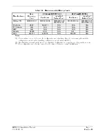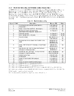
GMX 200 Installation Manual
Page v
190-00607-04 Revision
D
A.1
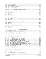
STC/PMA Information.................................................................................................................. A-1
A.2
Permission to use STC................................................................................................................... A-1
A.3
Continued Airworthiness Instructions ........................................................................................... A-1
A.4
STC Approved Model List ............................................................................................................ A-1
APPENDIX B - ENVIRONMENT QUALIFICATION FORM .............................................................. B-1
APPENDIX C - EQUIPMENT COMPATIBILITY................................................................................. C-1
C.1
Position Source.............................................................................................................................. C-1
C.2
NAV Source .................................................................................................................................. C-1
C.3
Altitude Source.............................................................................................................................. C-1
C.4
Traffic Source................................................................................................................................ C-2
C.5
Weather Source ............................................................................................................................. C-2
C.6
TAWS Source................................................................................................................................ C-3
C.7
Data Link ....................................................................................................................................... C-3
APPENDIX D - ASSEMBLY AND INSTALLATION DRAWINGS .................................................... D-1
D.1
Introduction ................................................................................................................................... D-1
D.2
Diagram List.................................................................................................................................. D-1
APPENDIX E – INTERCONNECT DIAGRAMS................................................................................... E-1
E.1
Introduction ................................................................................................................................... E-1
E.2
Diagram List.................................................................................................................................. E-1
LIST OF FIGURES
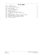
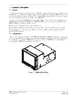
Figure 1-1. GMX 200 Unit View...............................................................................................................1-1
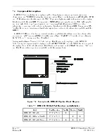
Figure 1-2. Example of a GMX 200 System Block Diagram ...................................................................1-2
Figure 1-3. Example of a GMX 200 I/O System Block Diagram.............................................................1-3
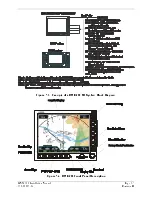
Figure 1-4. GMX 200 Front Panel Description ........................................................................................1-3
Figure 3-1. Shield Block Install onto Backshell Connector Assembly.....................................................3-5
Figure 3-2. Shielded Cable Preparation ....................................................................................................3-6
Figure 3-3. Configuration Module Installation .........................................................................................3-8
Figure 3-4. Backshell Assembly to Mounting Tube Installation ..............................................................3-9
Figure D-1. Connector Location ..............................................................................................................D-2
Figure D-2. Cockpit Panel Configuration for a Large Panel ...................................................................D-3
Figure D-3. Cockpit Panel Configuration for a Small Panel ...................................................................D-3
Figure D-4. Maximum Vertical Viewing Angle (Side View)..................................................................D-4
Figure D-5. Sample GNS 480 and GMX 200 Mounting with GNS 480 .................................................D-5
Figure D-6. GMX 200 Mounting Tube Assembly Dimensions...............................................................D-6
Figure D-7. GMX 200 and GMX 200 I/O Dimensions and Center of Gravity .......................................D-7
Figure E-1. Power and Configuration Module......................................................................................... E-3
Figure E-2. GPS Position Source............................................................................................................. E-4
Figure E-3. RS-232 Interfaces ................................................................................................................. E-5
Figure E-4. Stormscope ........................................................................................................................... E-6
Figure E-5. GDL 69/69A Data Link ........................................................................................................ E-7
Figure E-6. GDL 90 Data Link (Includes Traffic)................................................................................... E-8
Figure E-7. Traffic ................................................................................................................................... E-9
Figure E-8. TAWS ................................................................................................................................. E-10
Figure E-9. Weather Radar .................................................................................................................... E-11
Figure E-10. ARINC 453 Wiring for Multiple Radar Indicators........................................................... E-13
Содержание GMX 200
Страница 1: ...190 00607 04 March 2007 Revision D GMX 200 Installation Manual ...
Страница 4: ...Page ii GMX 200 Installation Manual Revision D 190 00607 04 This Page Intentionally Left Blank ...
Страница 18: ...Page 2 4 GMX 200 Installation Manual Revision D 190 00607 04 This Page Intentionally Left Blank ...
Страница 26: ...Page 3 8 GMX 200 Installation Manual Revision D 190 00607 04 Figure 3 3 Configuration Module Installation ...
Страница 34: ...Page 4 6 GMX 200 Installation Manual Revision D 190 00607 04 This Page Intentionally Left Blank ...
Страница 64: ...Page 5 30 GMX 200 Installation Manual Revision D 190 00607 04 This Page Intentionally Left Blank ...
Страница 72: ...Page 7 2 GMX 200 Installation Manual Revision D 190 00607 04 This Page Intentionally Left Blank ...
Страница 74: ...Page 8 2 GMX 200 Installation Manual Revision D 190 00607 04 This Page Intentionally Left Blank ...
Страница 76: ...Page A 2 GMX 200 Installation Manual Revision D 190 00607 04 This Page Intentionally Left Blank ...
Страница 78: ...Page B 2 GMX 200 Installation Manual Revision D 190 00607 04 This Page Intentionally Left Blank ...
Страница 82: ...Page C 4 GMX 200 Installation Manual Revision D 190 00607 04 This Page Intentionally Left Blank ...
Страница 90: ...Page D 8 GMX 200 Installation Manual Revision D 190 00607 04 This Page Intentionally Left Blank ...
Страница 92: ...Page E 2 GMX 200 Installation Manual Revision D 190 00607 04 This Page Intentionally Left Blank ...
Страница 102: ...Page E 12 GMX 200 Installation Manual Revision D 190 00607 04 This Page Intentionally Left Blank ...
Страница 104: ...Page E 14 GMX 200 Installation Manual Revision D 190 00607 04 This Page Intentionally Left Blank ...
Страница 105: ......
Страница 106: ......


