Page 5-16
GMX 200 Installation Manual
Revision D
190-00607-04
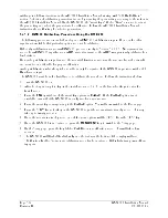
4. Set the tilt table to 10
°
pitch down. The PITCH ANGLE value should be 10.0D
±
1.0
°
. If the value
is out of range, repeat steps in Sections 5.4.1.2.3 and 5.4.1.2.5 (this section).
5. Set the tilt table to 0
°
pitch. The PITCH ANGLE value should be 0.0
±
1.0
°
. If the value is out of
range, repeat steps in Sections 5.4.1.2.3 and 5.4.1.2.5 (this section).
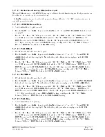
5.4.1.2.6 Roll Gain
1. Set the tilt table for 10
°
roll right.
2. Use the GAIN + and GAIN – keys to set the GAIN to between -21 and -23. The AZIMUTH ANGLE
field should also display 03. Note that the roll gain value is displayed in the ROLL ANGLE field.
3. Use the TILT and TILT
keys to adjust the TILT SETTING. A TILT SETTING between 5 UP
and 10 UP increases the ROLL ANGLE field, while a TILT SETTING between 5 DOWN and 10
DOWN decreases the ROLL ANGLE field. Use the TILT keys to set the ROLL ANGLE field to
10.0
±
1.0
°
. Upon reaching the desired ROLL ANGLE setting, quickly set the TILT SETTING to
between 5 UP and 5 DOWN to lock in the ROLL ANGLE setting.
4. Set the tilt table to 10
°
roll left. The ROLL ANGLE value should be 10.0L
±
1.0
°
. If the value is out
of range, repeat steps in Sections 5.4.1.2.4 and 5.4.1.2.6 (this section).
5. Set the tilt table to 0
°
roll. The ROLL ANGLE value should be 0.0
±
1.0
°
. If the value is out of
range, repeat steps in Sections 5.4.1.2.4 and 5.4.1.2.6 (this section).
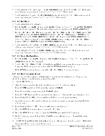
5.4.1.2.7 Save Configuration
1.
Use the GAIN + and GAIN – keys to set the GAIN to between -3.5and -5.5. The AZIMUTH
ANGLE field should also display 08.
2.
Set the TILT SETTING to 15.0D. The fault fields will flash on indicating the save procedure is
beginning. If the save procedure is successful, the GYRO fault will disappear.
3.
If the GYRO remains unchanged, adjust the TILT SETTING to 0
°
and repeat step 2.
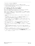
5.4.1.2.8 Roll Trim Adjustment
This procedure must be performed in flight with an operational, transmitting radar. This procedure
should be performed over flat terrain or water if possible.
1.
Turn the GMX 200 on.
2.
After boot-up is complete, key-in the install sequence 1, 4, 6, on the smart keys.
3.
Press the
FN
key until one of the smart key options is RADAR.
4.
Press the smart key corresponding to the RADAR option.
5.
Press the STBY key to put the radar unit into standby mode. This may take up to twenty seconds.
6.
Press the key labeled ON. The radar will enter WX mode and begin transmitting.
7.
Adjust the range and tilt controls so that ground returns are painted past approximately half of the
selected range.
8.
Press they key labeled STBY. The radar will return to standby mode.
9.
Once the GWX 68 is in standby mode, press the TEST key.
10.
Once the GWX 68 is in Test mode, press the ENTER key to switch to the Setup page.
11.
On the Setup page, press the key labeled CALB to enter calibration mode. This will take a few
seconds.
12.
The GMX 200 will flash all faults briefly to indicate calibration mode has been entered. If this fails,
turn power off and on and repeat the procedure.
Содержание GMX 200
Страница 1: ...190 00607 04 March 2007 Revision D GMX 200 Installation Manual ...
Страница 4: ...Page ii GMX 200 Installation Manual Revision D 190 00607 04 This Page Intentionally Left Blank ...
Страница 18: ...Page 2 4 GMX 200 Installation Manual Revision D 190 00607 04 This Page Intentionally Left Blank ...
Страница 26: ...Page 3 8 GMX 200 Installation Manual Revision D 190 00607 04 Figure 3 3 Configuration Module Installation ...
Страница 34: ...Page 4 6 GMX 200 Installation Manual Revision D 190 00607 04 This Page Intentionally Left Blank ...
Страница 64: ...Page 5 30 GMX 200 Installation Manual Revision D 190 00607 04 This Page Intentionally Left Blank ...
Страница 72: ...Page 7 2 GMX 200 Installation Manual Revision D 190 00607 04 This Page Intentionally Left Blank ...
Страница 74: ...Page 8 2 GMX 200 Installation Manual Revision D 190 00607 04 This Page Intentionally Left Blank ...
Страница 76: ...Page A 2 GMX 200 Installation Manual Revision D 190 00607 04 This Page Intentionally Left Blank ...
Страница 78: ...Page B 2 GMX 200 Installation Manual Revision D 190 00607 04 This Page Intentionally Left Blank ...
Страница 82: ...Page C 4 GMX 200 Installation Manual Revision D 190 00607 04 This Page Intentionally Left Blank ...
Страница 90: ...Page D 8 GMX 200 Installation Manual Revision D 190 00607 04 This Page Intentionally Left Blank ...
Страница 92: ...Page E 2 GMX 200 Installation Manual Revision D 190 00607 04 This Page Intentionally Left Blank ...
Страница 102: ...Page E 12 GMX 200 Installation Manual Revision D 190 00607 04 This Page Intentionally Left Blank ...
Страница 104: ...Page E 14 GMX 200 Installation Manual Revision D 190 00607 04 This Page Intentionally Left Blank ...
Страница 105: ......
Страница 106: ......

