


GMX 200 Installation Manual
Page 3-7
190-00607-04 Revision
D
7.
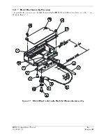
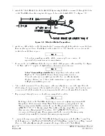
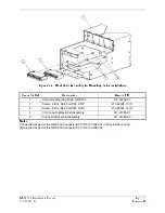
Wrap the cable bundle with Silicone Fusion Tape (12) (GPN: 249-00114-00 or a similar version) at
the point where the backshell strain relief and cast housing will contact the cable bundle.
8.
Place the smooth side of the backshell strain relief (13) across the cable bundle and secure using the
three screws (14). Warning: Placing the grooved side of the strain relief across the cable bundle may
damage wires.
9.
Attach the cover (15) to the backshell (1) using two screws (16).
3.4.2.2 Configuration Module Installation
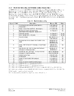
Table 3-4 lists part numbers for the Configuration Module Kit, which is used with P2001 only.
Table 3-4. Configuration Module Kit – 011-00979-02
Figure 3-3 Ref
Description
Garmin P/N
1
Configuration Module, PCB Board Assembly w/EEPROM
012-00605-00
2
Spacer, Config Module
213-00043-00
3 4-Conductor
Harness
325-00122-00
4
Socket Contact, Crimp, #20
336-00022-01
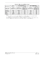
Table 3-5. Configuration Module Wire Color Reference Chart
Color Function
P2001
Contact
Black Ground
27
Red Vcc 24
Yellow Data
19
White Clock
17
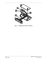
Assemble the configuration module as follows:
1.
Crimp socket contacts (4) onto each wire of the four-conductor wire harness (3). Strip 1/8” of
insulation from each wire prior to crimping.
2.
Insert newly crimped socket contacts and wires (3, 4) into the appropriate connector housing
location as shown in Figure 3-3.
3.
Apply the spacer (2) by wrapping it around the PCB Board (1) making sure to insert the plastic
connector mounted on the board into the hole provided in the spacer.
4.
Plug the four-conductor wire harness (3) into the connector on the PCB Board (1).
5.
With pad (2) in position, insert PCB Board (1) into the backshell recess.
6.
Orient the connector housing so that the inserted four conductor wire harness (3) is on the same
side of the backshell as the inserted PCB Board (1), as shown in Figure 3-3.
7.
Attach cover to backshell using screws.
Содержание GMX 200
Страница 1: ...190 00607 04 March 2007 Revision D GMX 200 Installation Manual ...
Страница 4: ...Page ii GMX 200 Installation Manual Revision D 190 00607 04 This Page Intentionally Left Blank ...
Страница 18: ...Page 2 4 GMX 200 Installation Manual Revision D 190 00607 04 This Page Intentionally Left Blank ...
Страница 26: ...Page 3 8 GMX 200 Installation Manual Revision D 190 00607 04 Figure 3 3 Configuration Module Installation ...
Страница 34: ...Page 4 6 GMX 200 Installation Manual Revision D 190 00607 04 This Page Intentionally Left Blank ...
Страница 64: ...Page 5 30 GMX 200 Installation Manual Revision D 190 00607 04 This Page Intentionally Left Blank ...
Страница 72: ...Page 7 2 GMX 200 Installation Manual Revision D 190 00607 04 This Page Intentionally Left Blank ...
Страница 74: ...Page 8 2 GMX 200 Installation Manual Revision D 190 00607 04 This Page Intentionally Left Blank ...
Страница 76: ...Page A 2 GMX 200 Installation Manual Revision D 190 00607 04 This Page Intentionally Left Blank ...
Страница 78: ...Page B 2 GMX 200 Installation Manual Revision D 190 00607 04 This Page Intentionally Left Blank ...
Страница 82: ...Page C 4 GMX 200 Installation Manual Revision D 190 00607 04 This Page Intentionally Left Blank ...
Страница 90: ...Page D 8 GMX 200 Installation Manual Revision D 190 00607 04 This Page Intentionally Left Blank ...
Страница 92: ...Page E 2 GMX 200 Installation Manual Revision D 190 00607 04 This Page Intentionally Left Blank ...
Страница 102: ...Page E 12 GMX 200 Installation Manual Revision D 190 00607 04 This Page Intentionally Left Blank ...
Страница 104: ...Page E 14 GMX 200 Installation Manual Revision D 190 00607 04 This Page Intentionally Left Blank ...
Страница 105: ......
Страница 106: ......