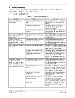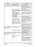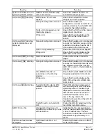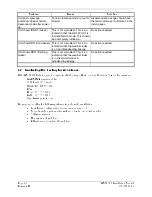
GMX 200 Installation Manual
Page 7-1
190-00607-04 Revision
D
7 Limitations
7.1 Operation
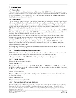
There are no Part 23 aircraft type limitations. All functions of the GMX 200 meet the appropriate design
assurance qualifications for a secondary system for airplanes in Class I, Class II, Class III, and Class IV in
accordance with AC 23.1309-1C, Figure 2. The TSO authorizations with the RTCA/DO178B software
levels by function are listed in Section 1.6.
7.2 Installation
The conditions and tests required for TSO approval of this article are minimum performance standards. It
is the responsibility of those installing this article either on or within a specific type or class of aircraft to
determine that the aircraft installation conditions are within the TSO standards. TSO articles must have
separate approval for installation in an aircraft. The article may be installed only if performed under 14
CFR Part 43 or the applicable airworthiness requirements.
If it is necessary to move any required instrumentation in an instrument panel to make room for the GMX
200, although the physical mounting of the GMX 200 is covered within this installation manual, the
relocation of these instruments is beyond the scope of the STC.
For installations where a 6.25” wide radio structure of adequate height is not already approved in the
aircraft, a separate structural approval is needed for installation of such supporting structure, prior to
installing the GMX 200. Such modifications are beyond the scope of this STC.
In order to provide optimal display view ability (and limit any color shift), the GMX 200 must be
installed at a height in the panel so that the pilot’s eye will not exceed the 30° downward view to the
display as illustrated in Figure D-4.
For preservation of essential equipment in aircraft with multiple power busses the GMX 200 should be
powered from the non-essential bus.
7.2.1 Equipment Interfaced to the GMX 200
GMX 200 interfaces to aircraft systems other than those shown in this installation manual are outside the
scope of this manual and may require further evaluation and/or certification approval.
All equipment interfaced to the GMX 200 must be previously or concurrently approved.
7.2.1.1 Traffic Sensor
Only one traffic sensor may be installed.
7.2.1.2 FIS Sensor
FIS data from only one sensor is used by the GMX 200. When a GDL 69/69A and GDL 90 are installed,
the GMX 200 will process the FIS data from the GDL 69/69A and traffic data from the GDL 90, ignoring
the FIS data from the GDL 90.
7.2.1.3 Terrain Sensor
Only one TAWS sensor may be installed. Configuration of TAWS sensor and internal terrain function
are mutually exclusive.
7.2.1.4 Radar Sensor
Only one radar sensor may be installed.
7.2.2 Preservation of Previous Systems
It is the installer’s responsibility to preserve the essential characteristic of the aircraft being modified by
this manual to be in accordance with the aircraft manufacturer’s original design. This includes the
preservation of multiple power buses, which reduce the probability of interrupting power to essential
instruments and avionics.
Содержание GMX 200
Страница 1: ...190 00607 04 March 2007 Revision D GMX 200 Installation Manual ...
Страница 4: ...Page ii GMX 200 Installation Manual Revision D 190 00607 04 This Page Intentionally Left Blank ...
Страница 18: ...Page 2 4 GMX 200 Installation Manual Revision D 190 00607 04 This Page Intentionally Left Blank ...
Страница 26: ...Page 3 8 GMX 200 Installation Manual Revision D 190 00607 04 Figure 3 3 Configuration Module Installation ...
Страница 34: ...Page 4 6 GMX 200 Installation Manual Revision D 190 00607 04 This Page Intentionally Left Blank ...
Страница 64: ...Page 5 30 GMX 200 Installation Manual Revision D 190 00607 04 This Page Intentionally Left Blank ...
Страница 72: ...Page 7 2 GMX 200 Installation Manual Revision D 190 00607 04 This Page Intentionally Left Blank ...
Страница 74: ...Page 8 2 GMX 200 Installation Manual Revision D 190 00607 04 This Page Intentionally Left Blank ...
Страница 76: ...Page A 2 GMX 200 Installation Manual Revision D 190 00607 04 This Page Intentionally Left Blank ...
Страница 78: ...Page B 2 GMX 200 Installation Manual Revision D 190 00607 04 This Page Intentionally Left Blank ...
Страница 82: ...Page C 4 GMX 200 Installation Manual Revision D 190 00607 04 This Page Intentionally Left Blank ...
Страница 90: ...Page D 8 GMX 200 Installation Manual Revision D 190 00607 04 This Page Intentionally Left Blank ...
Страница 92: ...Page E 2 GMX 200 Installation Manual Revision D 190 00607 04 This Page Intentionally Left Blank ...
Страница 102: ...Page E 12 GMX 200 Installation Manual Revision D 190 00607 04 This Page Intentionally Left Blank ...
Страница 104: ...Page E 14 GMX 200 Installation Manual Revision D 190 00607 04 This Page Intentionally Left Blank ...
Страница 105: ......
Страница 106: ......

