Page 3-2
GMX 200 Installation Manual
Revision D
190-00607-04
3.3.2 Unit Replacement
Whenever the GMX 200 is removed and reinstalled, verify that the GMX 200 unit power-up self-test
sequence is successfully completed and no failure messages are annunciated. If the unit was serviced or if
a different unit is being installed, verify that the configuration is correct using the previously completed
checkout log prior to verifying that the GMX 200 unit power-up self-test sequence is successfully
completed and no failure messages are annunciated.
NOTE
The installation configuration settings are stored in the configuration module and will be
retained when the GMX 200 is replaced with a new unit. However, user settings are
stored on the SD card and will be lost when the GMX 200 is replaced with a new unit,
unless the SD card from the removed unit is installed in the new unit.
3.4 Cabling and Wiring
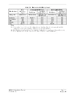
The GMX 200 installation kit includes connectors and crimp contacts. Make the crimp connections with a
crimp tool as specified in Table 3-2.
Refer to the interconnection diagrams in Appendix E for the appropriate interconnections. Use 22 or 24
AWG wire for all connections except for power. Use 20 AWG for power/ground. Install the
configuration module as described in Section 3.4.2.2. Once the cable assemblies have been made, attach
the backshell
/
connector to the rear of the mounting tube. Route the wiring bundle as appropriate. Avoid
sharp bends.
3.4.1 Wiring Harness
Allow adequate space for installation of cables and connectors. The installer supplies and fabricates all of
the cables. All electrical connections are made through a 37-pin D-Subminiature connector (and 62-pin
D-subminiature connector for the GMX 200 I/O) provided by Garmin. Construct the wiring harness
according to the information contained in this and the following sections. Cable lengths will vary
depending upon installation. Strip all wires going to the connectors 1/8”. Insert the wire into the pin and
crimp with one of the recommended (or equivalent) crimping tools. Insert the pin into the connector
housing location as specified by the interconnect drawing in Appendix E. Verify the pin is properly
engaged into the connector by gently tugging on the wire. Route and secure the cable run from the GMX
200 to the other units away from sources of electrical noise.
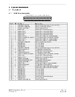
Section 4 provides I/O definition of all input and output signals. Required connectors and associated
hardware are supplied with the connector kit(s). See Appendix E for interconnect wiring diagrams.
CAUTION
Check wiring connections for errors before inserting the GMX 200 into the tube.
Incorrect wiring could cause component damage.
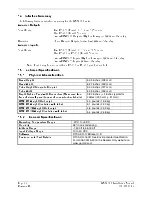
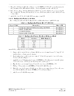
Table 3-1. Socket Contact Part Numbers
37-pin connector (P2001)
62-pin connector (P2002)
Wire Gauge
20-24 AWG
[1]
22-28 AWG
Garmin P/N
336-00022-00
336-00055-00
Military P/N
M39029/63-368
M39029/57-354
AMP N/A
N/A
Positronic N/A
N/A
ITT Cannon
N/A
N/A
Содержание GMX 200
Страница 1: ...190 00607 04 March 2007 Revision D GMX 200 Installation Manual ...
Страница 4: ...Page ii GMX 200 Installation Manual Revision D 190 00607 04 This Page Intentionally Left Blank ...
Страница 18: ...Page 2 4 GMX 200 Installation Manual Revision D 190 00607 04 This Page Intentionally Left Blank ...
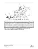
Страница 26: ...Page 3 8 GMX 200 Installation Manual Revision D 190 00607 04 Figure 3 3 Configuration Module Installation ...
Страница 34: ...Page 4 6 GMX 200 Installation Manual Revision D 190 00607 04 This Page Intentionally Left Blank ...
Страница 64: ...Page 5 30 GMX 200 Installation Manual Revision D 190 00607 04 This Page Intentionally Left Blank ...
Страница 72: ...Page 7 2 GMX 200 Installation Manual Revision D 190 00607 04 This Page Intentionally Left Blank ...
Страница 74: ...Page 8 2 GMX 200 Installation Manual Revision D 190 00607 04 This Page Intentionally Left Blank ...
Страница 76: ...Page A 2 GMX 200 Installation Manual Revision D 190 00607 04 This Page Intentionally Left Blank ...
Страница 78: ...Page B 2 GMX 200 Installation Manual Revision D 190 00607 04 This Page Intentionally Left Blank ...
Страница 82: ...Page C 4 GMX 200 Installation Manual Revision D 190 00607 04 This Page Intentionally Left Blank ...
Страница 90: ...Page D 8 GMX 200 Installation Manual Revision D 190 00607 04 This Page Intentionally Left Blank ...
Страница 92: ...Page E 2 GMX 200 Installation Manual Revision D 190 00607 04 This Page Intentionally Left Blank ...
Страница 102: ...Page E 12 GMX 200 Installation Manual Revision D 190 00607 04 This Page Intentionally Left Blank ...
Страница 104: ...Page E 14 GMX 200 Installation Manual Revision D 190 00607 04 This Page Intentionally Left Blank ...
Страница 105: ......
Страница 106: ......


