


__________________________________________________________________
Cirrus Perspective™ Line Maintenance Manual
Page 7-47
190-00920-00
Rev.
E
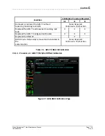
7.5.2
GDC
Testing
NOTE
Allow
unit
to
warm
up
for
15
minutes
before
performing
the
following
tests.
Verification
of
the
altimeter
and
airspeed
must
be
performed
using
a
pitot/static
ramp
tester.
The
static
port
and
altimeter
must
be
verified
in
accordance
with
Title
14
of
the
Code
of
Federal
Regulations
(CFR)
§
91.411
and
Part
43,
Appendix
E.
The
MFD
must
be
in
reversionary
mode
to
perform
the
tests
outlined
in
Appendix
E.
7.5.2.1
Preparing
the
Perspective™
System
for
Part
43
Appendix
E
Testing
1.
Press
and
hold
the
ENT
key
on
the
PFD
and
apply
system
power.
Allow
the
MFD
to
start
in
normal
mode.
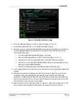
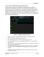
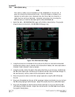
2.
On
the
PFD,
rotate
the
FMS
knob
to
until
the
display
shows
the
GRS
page
group.
Within
the
AIR
DATA
1
and
AIR
DATA
2
(in
dual
ADC
installations
only)
sub
windows
is
the
field
“B
ALT”
which
is
Barometric
Altitude.
B
ALT
is
equivalent
to
the
altitude
that
will
be
displayed
to
the
pilot
on
the
altitude
display.
B
ALT
will
be
used
for
all
CFR
Part
43
Appendix
E
tests
for
system
altitude.
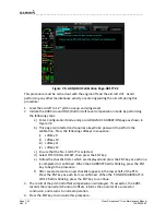
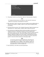
3.
Push
the
red
reversionary
button
located
between
the
displays.
This
activates
the
reversionary
mode
for
the
MFD.
Baro
settings
can
now
be
read
from
the
MFD
for
the
CFR
Part
43
Appendix
E
tests.
4.
When
viewing
the
baro
setting
for
the
second
GDC
in
dual
installations,
press
the
”SENSORS”
softkey
on
the
MFD
and
then
select
“ADC
2”.
5.
After
completing
the
tests
specified
by
§
91.411
and
Part
43
Appendix
E,
return
the
MFD
back
to
normal
mode
by
pushing
the
reversionary
button.
NOTE
The
following
tests
are
beyond
the
requirements
set
forth
in
Appendix
E.
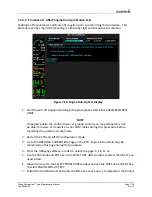
7.5.2.2
Airspeed
Test
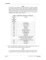
1.
Use
an
Air
Data
Test
Set
(ADTS)
to
simulate
air
speeds
shown
in
the
table
below.
Wait
for
the
ADTS
to
report
that
target
values
have
been
achieved.
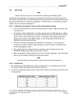
2.
Verify
that
computed
air
speeds
shown
on
the
PFD
are
within
the
tolerances
specified
in
the
following
table:
Calibrated
air
speed,
knots
Allowed
tolerance,
±knots
50
5.0
80
3.5
100
2.0
120
2.0
150
2.0
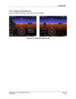
3.
Press
the
“SENSOR”
PFD
softkey
and
then
select
ADC2
(if
equipped).
Repeat
steps
1
and
2.


