


__________________________________________________________________
Page 7-28
Cirrus Perspective™ Line Maintenance Manual
Rev. E
190-00920-00
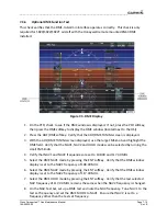
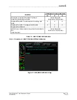
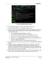
7.3.15
VOR
Test
1.
Simulate
a
VOR
signal
on
radial
360°
on
the
ramp
tester.
Tune
both
NAV1
and
NAV2
receivers
to
the
ramp
test
frequency.
2.
Set
the
HSI
on
the
PFD
to
VOR1
by
pressing
the
CDI
softkey.
Set
the
VOR1
CDI
course
to
360°
using
the
CRS
knob
on
the
GCU478.
3.
On
the
ramp
tester,
apply
a
10°
deviation
signal
in
both
right
and
left
directions
and
verify
full
scale
deflection
of
the
VOR1
CDI
in
the
corresponding
directions.
4.
On
the
ramp
tester,
set
the
signal
deviations
to
one
dot,
then
two
dots
deflection
in
both
right
and
left
directions.
Verify
proper
response
from
the
VOR1
CDI.
5.
Set
the
HSI
on
the
PFD
to
VOR2
by
pressing
the
CDI
softkey.
Set
the
VOR2
CDI
course
to
360°
using
the
CRS
knob
on
the
PFD.
6.
On
the
ramp
tester,
apply
a
10°
deviation
signal
in
both
right
and
left
directions
and
verify
full
scale
deflection
of
the
VOR2
CDI
in
the
corresponding
directions.
7.
On
the
ramp
tester,
set
the
signal
deviations
to
one
dot,
then
two
dots
deflection
in
both
right
and
left
directions.
Verify
proper
response
from
the
VOR2
CDI.
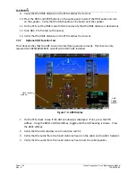
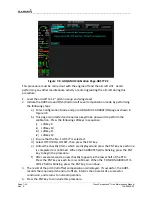
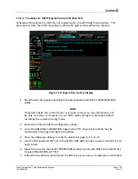
7.3.16
Localizer/Glideslope
Test
1.
Simulate
a
localizer
signal
on
the
ramp
tester.
Tune
both
NAV1
and
NAV2
receivers
to
the
ramp
test
frequency.
2.
Set
the
HSI
on
the
PFD
to
LOC1
by
pressing
the
CDI
softkey.
3.
On
the
ramp
tester
set
the
signal
deviations
to
one
dot,
then
two
dots
deflection
in
both
right
and
left
directions.
Verify
proper
response
from
the
LOC1
CDI.
4.
With
LOC1
CDI
selected,
exercise
the
Glideslope
deviation
indicator
with
up
and
down
deviation
indications
and
verify
the
Glideslope
deviation
indicator
responds
correctly
to
the
ramp
test
signal
deviations.
5.
Set
the
HSI
on
the
PFD
to
LOC2
by
pressing
the
CDI
softkey.
6.
On
the
ramp
tester
set
the
signal
deviations
to
one
dot,
then
two
dots
deflection
in
both
right
and
left
directions.
Verify
proper
response
from
the
LOC2
CDI.
7.
With
LOC2
CDI
selected
exercise
the
Glideslope
deviation
indicator
with
up
and
down
deviation
indications
and
verify
the
Glideslope
deviation
indicator
responds
correctly
to
the
ramp
test
signal
deviations.
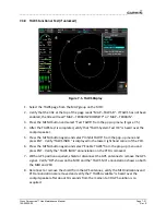
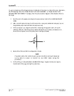
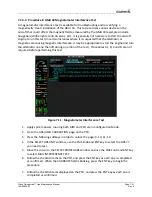
7.3.17
GFC
700
VOR/LOC/GS
Test
NOTE
Perform
this
test
only
if
the
aircraft
is
equipped
with
a
GFC
700.
1.
Simulate
a
VOR
signal
on
a
radial
which
corresponds
with
the
aircraft’s
current
heading.
Tune
the
NAV1
and
NAV2
receivers
to
the
correct
ramp
test
frequency.


