Garmin G5 Electronic Flight Instrument Part 23 AML STC Installation Manual
190-01112-10
Rev. 21
Page 219
- CONNECTOR INFORMATION
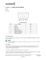
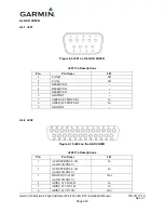
A.1 G5
A.1.1 J51
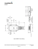
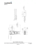
Figure 6-7 J51 on the G5
J51 Pin Descriptions
Pin
Pin Name
I/O
1
CAN-H
I/O
2
CAN-L
I/O
3
UNIT ID
In
4
RS-232 RX 1
In
5
RS-232 TX 1
Out
6
SIGNAL GROUND
--
7
AIRCRAFT POWER 1
In
8
AIRCRAFT POWER 2
In
9
POWER GROUND
--
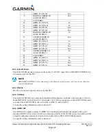
A.1.2 Aircraft Power
The G5 operates using power from one 14 / 28 VDC input. Pin 8 (AIRCRAFT POWER 2) is not used as
a part of this STC.
NOTE
AIRCRAFT POWER 2 is for connecting to an alternate power source, such as on aircraft with
two electrical buses.
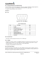
A.1.3 RS-232
The G5 has one RS-232 channel that may be used to interface to an existing GPS navigator or GPS
source to receive GPS data for attitude aiding. Also, the G5 RS-232 port can be used to receive
VHF and GPS navigation information.
For specific configuration settings for RS-232 refer to Section 6.3.6.2.
If an existing connection is made to the RS-232 port, the G5 connection can be spliced into the existing
wiring at the connector. For specific wiring information, refer to Section 5.

