Garmin G5 Electronic Flight Instrument Part 23 AML STC Installation Manual
190-01112-10
Rev. 21
Page 199
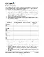
1.
*Consult the aircraft’s maintenance manual and locate the longitudinal (ROLL) and lateral
(PITCH) leveling points.
2.
Using a digital level, document the Aircraft Roll and Pitch offsets from these leveling points as
the aircraft sits on the landing gear. (Do not enter, exit, or move the aircraft at this point.) Use a
negative number for left wing up or nose up readings. Use a positive number for left wing down
or nose down readings.
3.
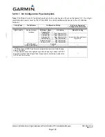
Select the Attitude Configuration Page.
4.
Select Calibrate Pitch/Roll.
5.
Ensure that aircraft and the unit comply with all on-screen instructions then select Start.
-Disregard item 1, leveling the aircraft is not necessary.
6.
A progress screen will then be displayed. There is a 30 second countdown timer for the procedure
that resets if the aircraft moves.
7.
When the calibration is complete, a successful status message will be displayed along with the
new pitch and roll offsets.
8.
If the leveling offsets documented from Step 2 were both 0.0, the calibration is complete. If
either new offset were other than 0.0, continue to step 9.
9.
Document the “New Roll Offset” and “New Pitch Offset” numbers and complete the equation.
10.
Press “Done” and adjust the values of the “Roll Calibration” and the “Pitch Calibration” values to
the answers from the equations.
NOTE
It is recommended that the adjusted “Roll Calibration” and the “Pitch Calibration” values from
step 10 be recorded in
Garmin G5 Electronic Flight Instrument Part 23 AML STC Maintenance
Manual including Instructions for Continued Airworthiness
, P/N 190-01112-11, Appendix A and
is retained with the aircraft permanent records.
11.
Exit Configuration Mode.
12.
This completes the Attitude Calibration Procedure.
*In flight level cruse attitude is not necessarily the same as the leveling points provided by the
manufacturer. Adjustments to the pitch and roll offsets can be made to compensate for the aircraft flight
characteristics.
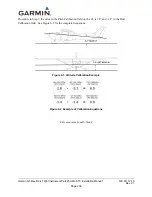
6.3.7.1.1 Attitude Calibration Example
In the Figure 6-1, the aircraft is sitting 5.2° nose up and 1.4° left wing up, (both negative number). Also,
the G5 is mounted in the pilot’s panel, which has an 8° forward tilt. After completing the Calibration

