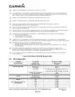
Garmin G5 Electronic Flight Instrument Part 23 AML STC Installation Manual
190-01112-10
Rev. 21
Page 132
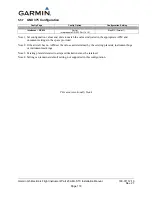
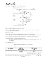
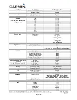
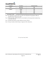
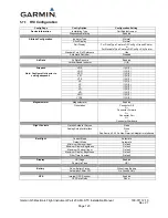
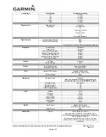
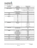
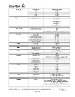
Config Page
Config Option
Configuration Setting
Roll Display
For Fixed Type Pointers G5 Config = Ground Pointer
or
For Movable Type Pointers G5 Config = Sky Pointer
Standard Turn Roll Reference
Hide
Automatic Declutter
Enabled
Air Data
Air Data Sensors
Enabled
Vertical Speed Indicator
(1)(2)
Airspeed
Note: Configure Units prior to setting
airspeeds.
VNE
(1)(2)(3)
VNO
(1)(2)(3)
VSO
(1)(2)(3)
VS1
(1)(2)(3)
VFE
(1)(2)(3)
VA
(1)(2)(3)
VX
(1)(2)(3)
VY
(1)(2)(3)
VG
(1)(2)(3)
VR
(1)(2)(3)
VMC
(1)(2)(3)
VYSE
(1)(2)(3)
Magnetometer
Magnetometer
Enabled
Orientation
Connector Aft
Or
Connector Forward
Or
Connector Port
Or
Connector Starboard
Flight Controls
Garmin Autopilot Servos
None
Analog Autopilot Interface
None
Or
See Section 5.23 if a Non-Garmin Autopilot is interfaced
Backlight
Current Mode
Automatic
Default Mode
Automatic
Minimum Photocell Input
Default
Minimum Display Brightness
Default
Maximum Photocell Input
Default
Maximum Display Brightness
Default
Filter Time Constant
Default
Display
HSI Page
Disabled
Power Up Page
PFD
Battery
Show Battery Status
When Using Battery
Automatic Power Off
On Ground Only
GPS
Internal GPS Receiver
Enabled
GPS Data Fields
Show
Navigation
Navigation Data
Disable
Note: If an autopilot interface is configured, this
configuration page is set to ENABLED by default.
Selected Course
(4)
VNAV Deviation Scale
(4)
Units
Altitude
(1)(2)
Distance
(1)(2)
Airspeed
(1)(2)(3)
Ground Speed
(1)(2)
Ground Track
Magnetic
Vertical Speed
(1)(2)
Pressure
(1)(2)

