Garmin G5 Electronic Flight Instrument Part 23 AML STC Installation Manual
190-01112-10
Rev. 21
Page 271
F.1.1.2
Landing Gear
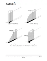
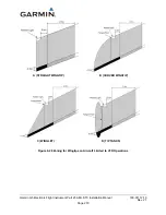
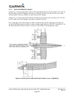
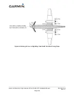
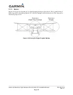
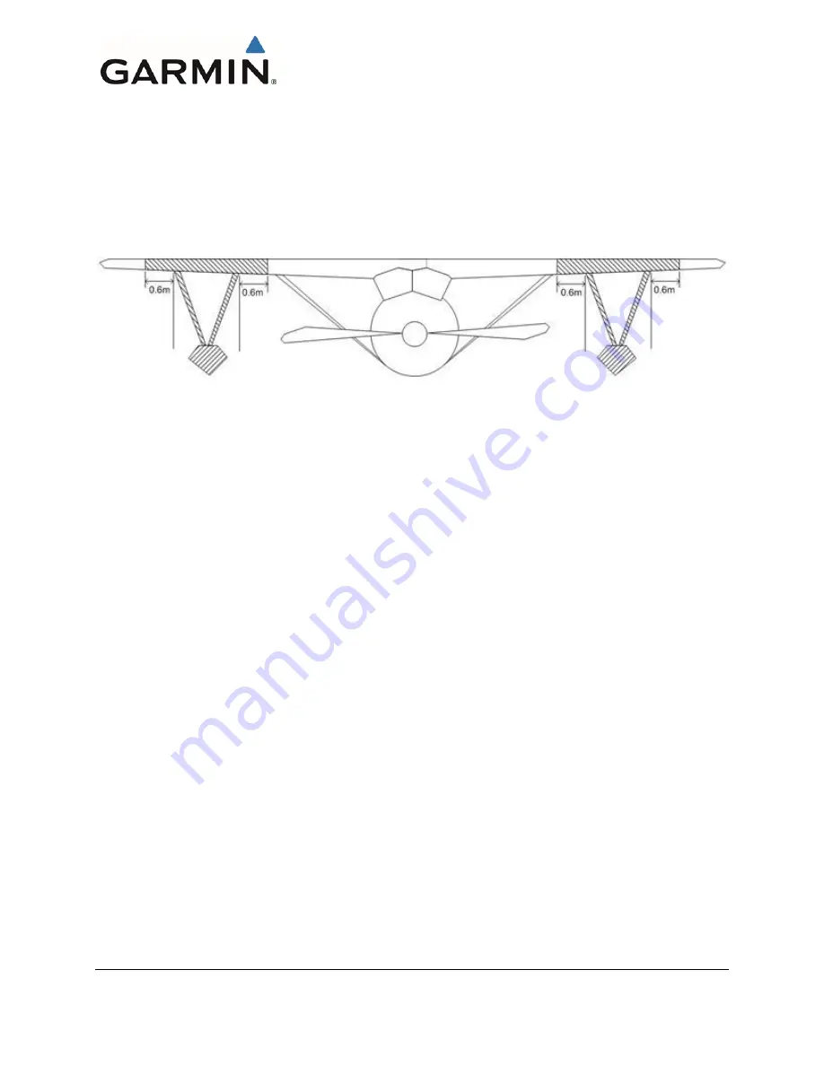
The landing gear is considered Zone 1A. The struts that connect the landing gear to the wings are Zone
2A. Each side of landing gear is zoned individually. If there is a single strut connecting the landing gear
to the wing, then the inboard and outboard edges of the landing gear should be used for zoning instead of
using the connection point of the wing and the strut. In addition to the zoning shown in Figure 6-29, the
zoning described for the fuselage and wings also applies. The floats for a float-mounted fuselage have not
been zoned because they do not influence the zoning of the bottom of the fuselage. The GTP 59 and
GMU11 cannot be mounted on landing gear, including floats, or its struts.
Figure 6-29 Zoning for Wings Affected by Landing Gear
F.1.2 Fuselage
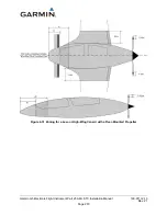
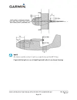
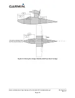
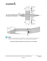
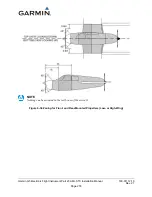
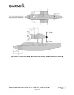
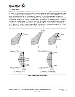
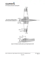
This section describes the zoning for several different types of fuselages. The empennage is zoned in
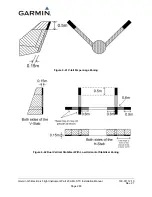
Appendix Section F.1.3. Aft of every Zone 2A is a 0.15 meter Zone 2B (i.e., Zone 2A is followed by a
0.15 meter Zone 2B). Although Zone 2B areas are marked on the diagrams, sometimes their widths are
not defined (0.15 meters should be used in these cases). The horizontal stabilizer of the tail is NOT zoned
because neither the GTP 59 nor the GMU 11 can be mounted there. In addition, neither the GTP 59 nor
the GMU 11 can be mounted within 0.5 meters of the rear-most point of the fuselage. Appendix Section
F.1.3 explains the conditions under which the GTP 59 or GMU 11 can be mounted on the vertical
stabilizer. Although all diagrams show low wing aircraft, the same zoning can be applied to high wing
aircraft. The values d1 and d2 are defined as follows:
d1 = 1.3m (51.2”)
d2 = 2.6m (102.4”)

