Garmin G5 Electronic Flight Instrument Part 23 AML STC Installation Manual
190-01112-10
Rev. 21
Page 100
3.
If the tape will come in contact with carbon composite material, the tape must be electrically
isolated from the carbon composite material to prevent corrosion due to dissimilar materials.
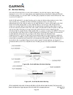
Secure a thin layer of fiberglass cloth to the carbon fiber with fiberglass resin as shown in Figure
4-58.
Figure 4-58 Fiberglass Insulation for Carbon Fiber Material
4.
Identify a grounding location. The ground must be a bare metal surface on the instrument panel or
grounding structure for the instrument panel. If it is impractical to reach a grounding location
with aluminum tape then:
a.
The tape shall meet a 5:1 length to width ratio.
b.
The bond strap shall be one inch wide and no longer than five inches.
5.
Prepare the aluminum surface at the ground location outlined in Section 4.5.3 or identify a ground
stud to which the braid can be attached. Any new ground stud shall also be prepared for electrical
bonding.
6.
Route the tape between the LRU mount and the grounding location for the instrument panel. If
needed to maintain the 7:1 length-to-width ratio, the tape can be overlapped in more than one
strip.
7.
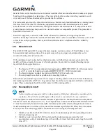
If two pieces of tape need to be joined end-to-end, they can be joined as illustrated in Figure 4-59.
Figure 4-59 Aluminum Tape Joint
8.
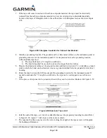
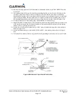
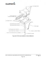
Fold the end of the tape over twice for added thickness at the prepared grounding location. Refer
to Figure 4-60. Apply 3” wide tape over the seam as shown.
9.
The tape shall not have any tears in the joint or along the length of the tape as tears will degrade
the bonding performance.

