Garmin G5 Electronic Flight Instrument Part 23 AML STC Installation Manual
190-01112-10
Rev. 21
Page 103
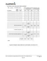
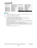
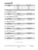
QQB575*34*375
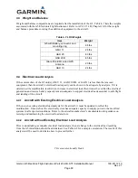
MS25036-112 (#10) or
MS25036-156 (#8)
AA59569*34*0375
MS25036-112 (#10) or
MS25036-156 (#8)
QQB575*32*375
MS25036-112 (#10) or
MS25036-156 (#8)
AA59569*32*0375
MS25036-112 (#10) or
MS25036-156 (#8)
QQB575*30*375
MS25036-115
AA59569*30*0375
MS25036-115
QQB575*30*473
MS25036-115
AA59569*36*0500
MS25036-115
QQB575*36*500
MS25036-115
AA59569*34*0500
MS25036-115
QQB575*34*500
MS25036-115
AA59569*32*0500
MS25036-115
QQB575*32*500
MS25036-115
AA59569*32*0500
MS25036-119
QQB575*30*500
MS25036-119
NOTE:
The following buildup instructions are only if the bonding strap being installed requires a #10
ring terminal for termination at a LRU backshell.
Create the bonding strap using the following instructions:
1.
Cut an appropriate length of a metal braid listed in the table (maximum 10 inches)
2.
Terminate both ends with the stated MS25036 terminal
3.
Find a location on structure to create or re-use an existing ground stud that is size #10 for
connection to this bonding strap from the LRU backshell.
4.
If creating a new ground stud, create a #10 ground stud in accordance with the instructions stated
in this section. Hole to be Ø0.201.
5.
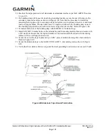
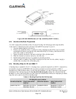
If using a #8 ring terminal for connection to the backshell, reference Figure 4-49 for hardware
buildup using ring terminal bonding strap part numbers listed in Table 4-9.
6.
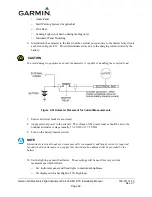
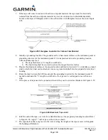
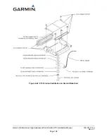
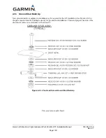
If using a #10 ring terminal for connection to the backshell, use the following method to connect
the #10 terminal to the LRU backshell, create the following hardware buildup as shown below in
Figure 4-62.
7.
Torque backshell hardware buildup to 11-17 in-lb.

