Garmin G5 Electronic Flight Instrument Part 23 AML STC Installation Manual
190-01112-10
Rev. 21
Page 109
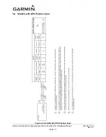
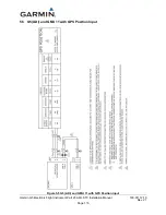
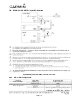
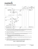
5.3 G5 (ADI) with a GPS Antenna
Figure 5-3 G5 (ADI) with a GPS Antenna
5.3.1
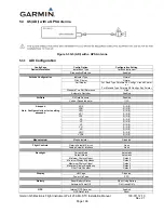
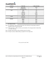
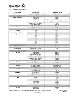
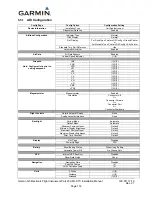
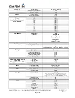
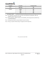
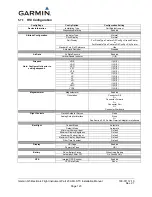
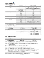
ADI Configuration
Config Page
Config Option
Configuration Setting
Device Information
Installation Type
Certified Instrument
Diagnostics/Data Log
Enabled
Attitude Configuration
Indicator Type
Normal
Pitch Display
Normal
Roll Display
For Fixed Type Pointers G5 Config = Ground Pointer
or
For Movable Type Pointers G5 Config = Sky Pointer
Standard Turn Roll Reference
Hide
Automatic Declutter
Enabled
Air Data
Air Data Sensors
Enabled
Vertical Speed Indicator
(1)(2)
Airspeed
Note: Configure Units prior to setting
airspeeds.
VNE
(1)(2)(3)
VNO
(1)(2)(3)
VSO
(1)(2)(3)
VS1
(1)(2)(3)
VFE
(1)(2)(3)
VA
(1)(2)(3)
VX
(1)(2)(3)
VY
(1)(2)(3)
VG
(1)(2)(3)
VR
(1)(2)(3)
VMC
(1)(2)(3)
VYSE
(1)(2)(3)
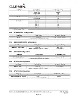
Magnetometer
Magnetometer
Disabled
Flight Controls
Garmin Autopilot Servos
None
Analog Autopilot Interface
None
Backlight
Current Mode
Automatic
Default Mode
Automatic
Minimum Photocell Input
Default
Minimum Display Brightness
Default
Maximum Photocell Input
Default
Maximum Display Brightness
Default
Filter Time Constant
Default
Display
HSI Page
Disabled
Power Up Page
PFD
Battery
Show Battery Status
When Using Battery
Automatic Power Off
On Ground Only
GPS
Internal GPS Receiver
Enabled
GPS Data Field
Show

