Garmin G5 Electronic Flight Instrument Part 23 AML STC Installation Manual
190-01112-10
Rev. 21
Page 205
6.3.7.4.1 Compass Swing
After the Magnetic Calibration Procedure is completed, a compass swing must be performed to verify
the GMU 11 heading accuracy. If each heading displayed on the G5 (or G5 #1 and G5 #2) is within
±10° of the actual heading no further adjustments are necessary.
1.
With the G5(or G5 #1 and G5 #2 for a dual G5 installation) in normal mode, all of the aircraft
and avionics systems powered and operating normally, position the aircraft on a known compass
rose at a heading 360° (North), or select a level and magnetically clean location and use a sight
compass to position the aircraft to a heading of 360° (North).
2.
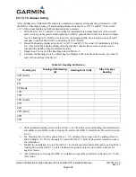
Record the heading displayed on the G5 (or G5 #1 and G5 #2 for a dual G5 installation) in Table
6-2. Also record the heading displayed on the standby compass (these values can be used to
complete the standby compass calibration card).
3.
Repeat step 2 for each of the headings listed in Table 6-2.
4.
Calculate the heading errors by subtracting the displayed (B) value from the actual (A) value for
each of the headings in Table 6-2.
Table 6-2: Heading Verification
Heading (A)
Displayed G5 Heading
(B)
Heading Error (A-B)
Stby Compass
Heading
360º (North)
30º
60º
90º (East)
120º
150º
180º (South)
210º
240º
270º (West)
300º
330º
5.
If all calculated heading errors for the G5 are +/-10° from the surveyed heading, the installation is
acceptable and no further work is required to correct the GMU 11 installation. Proceed to Section
6.3.8.3.
6.
If a Heading Error (A-B) is greater than +/- 10°, calculate the average error by adding all errors
and dividing by 12. This is the angle by which the GMU 11 must be physically rotated to correct
the installation.
7.
Modify the installation to rotate the GMU 11 by the amount calculated in the previous step. When
looking down at the GMU 11, rotate clockwise for positive values, and counterclockwise for
negative values.
8.
After physically correcting the GMU 11 installation, repeat the procedures in Section 6.3.7.4 and
this section.

