Garmin G5 Electronic Flight Instrument Part 23 AML STC Installation Manual
190-01112-10
Rev. 21
Page 101
10.
Electrical bond preparation for all aluminum-to-aluminum interfaces per SAE ARP1870 section
5.1 and 5.5.
11.
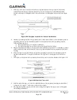
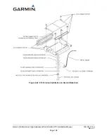
If a bonding strap will be used to reach the grounding location, secure the end of the tape to the
secondary composite surface as shown in Figure 4-60. Note that the procedure for installing
mounting bolts applies only to secondary aircraft structures, not to primary structure or structural
load-carrying members. The tape shall meet 5:1 length to width ratio if a bonding strap is used.
The bonding strap shall be one inch wide and no longer than five inches. Refer to Figure 4-60.
12.
Terminate both ends of the bonding strap with MS20659-130 terminal lugs.
13.
Install AN960C10 washer between the terminal lug and the mating metal surface and secure with
a #10 steel bolt. Ensure that the lug and washer are centered and in full contact with the mating
surface with no overhang when secured.
14.
Secure the end of the tape in place using a 0.063” piece of aluminum using three bolts and nuts.
Refer to Figure 4-60.
15.
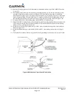
Secure the aluminum tape to the GAD 29/29B, GAD 13, or mounting rack as shown in Figure
4-61.
16.
Verify that the resistance between tape and the local grounding location does not exceed 2.5 mΩ.
Figure 4-60 Aluminum Tape Ground Termination

