Garmin G5 Electronic Flight Instrument Part 23 AML STC Installation Manual
190-01112-10
Rev. 21
Page 213
3.
Once G5(s) have initialized on the HSI (if installed):
a.
Remove power from the G5 ADI (if installed).
Note:
Manual reversion to HSI format may be required.
b.
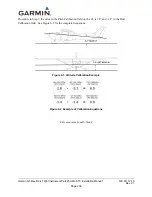
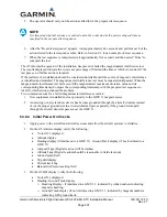
Verify crosswind information box is displayed on the HSI.
Note:
If crosswinds display as NO WIND DATA this is acceptable.
c.
If only a G5 HSI is installed, verify the OAT is shown and valid in the bottom left hand
corner of the G5 HSI.
Figure 6-5 HSI Display of Crosswind (Typical Values Shown)
6.3.10
Electromagnetic Compatibility (EMC) Check
An EMC check must be conducted once the G5(s) and supporting equipment is installed and all
interfaces to external equipment are verified to be correctly working. The EMC check makes sure the
equipment is not producing unacceptable interference to the other avionics systems, and other avionics
systems are not producing unacceptable interference to the G5.
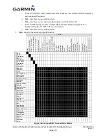
An example EMC Source/Victim matrix is shown in Figure 6-6.
1.
Enter equipment installed in the aircraft into the Source row and Victim column of the fillable
form.
2.
Apply power to all avionics systems except the equipment installed under this STC.
3.
Make sure all existing avionics systems are properly functioning.
4.
Apply power to the G5.
5.
Remove power from all other avionics systems.
6.
Apply power and/or operate the systems listed on the fillable form, one system at a time. Make
sure to pull/push circuit breakers or turn on/off large loads, e.g. heaters, cycling flaps (if
electrical) etc.
7.
Make sure the G5 properly functions.
a.
When the VHF COM is operating as a source, transmit on low/med/high unused
frequencies.
8.
Make sure each radio properly functions.
a.
For each VHF COM radio, monitor one local frequency, one remote (far field) frequency,
and one unused frequency.
b.
Make sure there are no unintended squelch breaks or audio tones interfere with
communications.

