Garmin G5 Electronic Flight Instrument Part 23 AML STC Installation Manual
190-01112-10
Rev. 21
Page 89
4.3 Weight and Balance
Weight and balance computations are required after the installation of the G5. Table 4-7 lists the weights
associated with the G5 Electronic Flight Instrument. Refer to AC 43.13-1B, Chapter 10, for the weight
and balance procedure covering the addition of equipment to the aircraft.
Table 4-7: LRU Weights
Item
Weight
G5 with Battery, connector and
mounting ring
.98 lbs
GMU 11
.26 lbs
GAD 29
.63 lbs
GAD 29B
.65 lbs
Glare Shield Mounted GPS
Antenna
.20 lbs
GAD 13
.24 lbs
4.4 Electrical Load Analysis
If the current draw of the G5 unit(s), GMU 11, GAD 29/29B, or GAD 13 is less than the removed
equipment, then the aircraft’s electrical load capacity can be shown to be adequate by analysis. If it is
determined the modification results in an increase in electrical load, then it must be verified the electrical
generation and reserve battery capacity remain adequate to support electrical loads essential to safe flight
and landing of the aircraft.
4.4.1
Aircraft with Existing Electrical Load Analysis
If there is an existing electrical load analysis for the aircraft, it must be updated to reflect the
modification. It must show the electrical system has adequate capacity to supply power to the modified
systems in all expected conditions. Refer to the aircraft manufacturer’s documentation for guidance on
revising and maintaining the electrical load analysis.
4.4.2
Aircraft without Existing Electrical Load Analysis
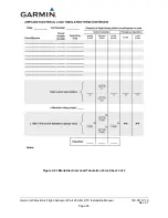
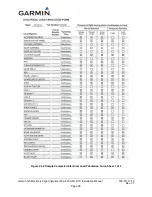
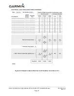
Prior to undertaking a complete electrical load analysis, the net change to the electrical load resulting
from the G5 installation should be determined. See Table 4-8 for a sample calculation. The results of this
analysis will be used to determine how to proceed further.
This area intentionally blank

