


Revision 14
75
August 02, 2019
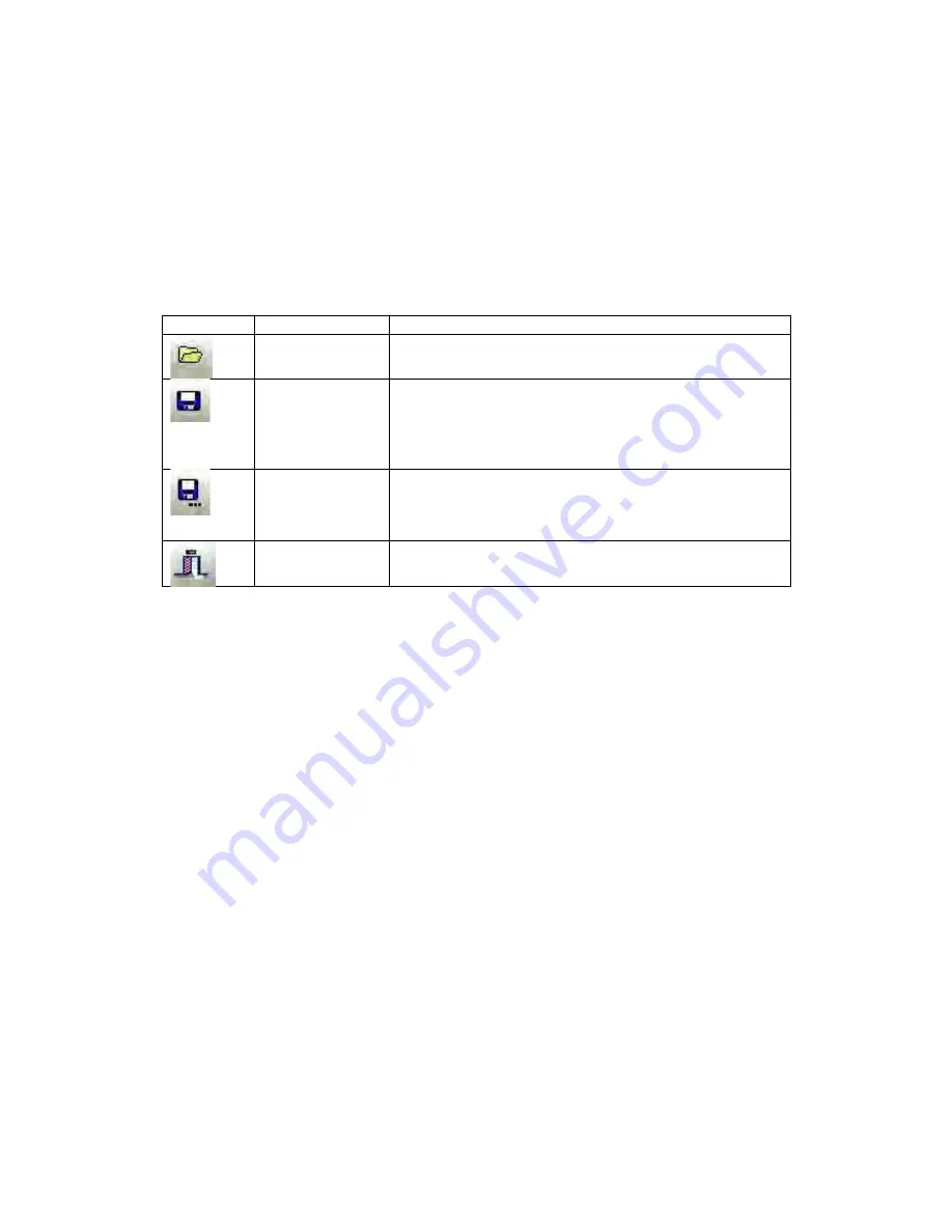
5.2.2.3 General Toolbar
The
General
toolbar contains several buttons that allow the user to load and save
configuration files, print configurations, and open the context selective help file. Table 5-3
shows the buttons in the
General
toolbar. A saved configuration file can be opened, edited
and re-saved when offline (not connected to the analyzer).
Table 5-3: General Toolbar Buttons
Button
Name
Function
Open
Opens a saved analyzer configuration file. This can be
done online or offline.
Save Current
Configuration
Saves current configuration to a file. If the configuration
has been saved to a file previously, pressing this button
will overwrite the existing configuration file. If offline, a
saved configuration file needs to be opened before one
can be saved.
Save
Configuration to
a new file
Saves current configuration to a new file with a file
name of the user’s choosing. If offline, a saved
configuration file needs to be opened before one can
be saved.
Exit
Pressing this button will cause the GUI to close. It is
advisable to log off the analyzer prior to exiting the GUI.
5.2.3 Application Screens (Tabs)
The GUI is a tab-driven system which includes the 17 tabs listed in Table 5-4. Each tab
contains information about the analyzer and most allow for editing of system parameters (in
Update
mode). The specifics of each tab will be discussed in Section 5.4 to 5.20.
Содержание ProTech903
Страница 2: ......
Страница 96: ...Revision 14 96 August 02 2019 Figure 5 19 Event Log...
Страница 122: ...Revision 14 122 August 02 2019 Figure 5 38 Typical Modicon with Floating Point List...
Страница 124: ...Revision 14 124 August 02 2019 Figure 5 40 Expanded Modbus Nodes...
Страница 167: ...Revision 14 167 August 02 2019 Figure 9 1 DC Power Wiring Diagram Figure 9 2 AC Power Wiring Diagram...
Страница 168: ...Revision 14 168 August 02 2019 Figure 9 3 Total Sulfur Wiring Diagram Figure 9 4 AC DC Power Wiring Diagram...
Страница 169: ...Revision 14 169 August 02 2019 Figure 9 5 Solenoid Drivers Wiring Diagram Figure 9 6 Relays Wiring Diagram...
Страница 173: ...Revision 14 173 August 02 2019 Figure 9 13 Isolated RS 485 Port Figure 9 14 P17 RS232 Port to Ethernet Cable...
Страница 175: ...Revision 14 175 August 02 2019 Figure 9 17 Non Isolated 4 20 mA Inputs...
Страница 190: ...Revision 14 190 August 02 2019...


