background image

683

APPENDIX C  Timing Diagrams in Flash Memory Mode

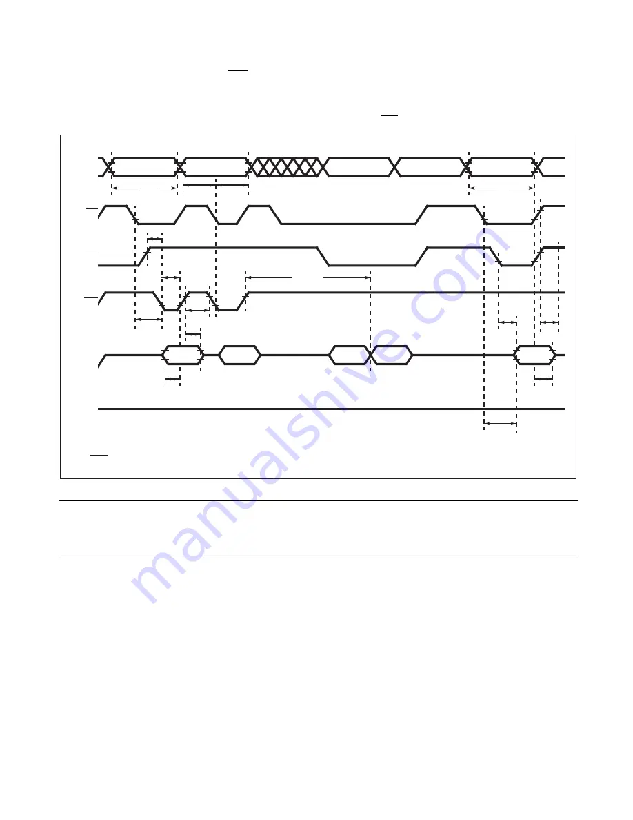
Write, Data Polling, Read (WE Control)

Figure C-2  Write, Data Polling, Read (WE Control)

Note:

The last two bus cycle sequences out of the four are described.

7AAAA

H

t

WC

Third bus cycle

PA

t

AS

t

AH

PA

t

WHWH1

t

WP

t

GHWL

t

CS

t

WPH

t

DH

t

DS

A0

H

PD

DQ7

D

OUT

t

OH

t

DF

t

CE

t

OE

Data polling

PA: Write 

address

PD: Write 

data

DQ7: Reverse 

output 

of 

w

rite data

D

OUT

: Output 

of 

w

rite data

t

RC

AQ18

 to

 AQ0

CE

OE

WE

DQ7

 to

 DQ0

5.0 V

Содержание MB90390 Series

Страница 1: ...FUJITSU MICROELECTRONICS CONTROLLER MANUAL F2MC 16LX 16 BIT MICROCONTROLLER MB90390 Series HARDWARE MANUAL CM44 10122 4E ...

Страница 2: ......

Страница 3: ...ller supports is shown in the following homepage Be sure to refer to the Check Sheet for the latest cautions on development Check Sheet is seen at the following support page Check Sheet lists the minimal requirement items to be checked to prevent problems beforehand in system development http edevice fujitsu com micom en support ...

Страница 4: ......

Страница 5: ...nder the Philips I2 C Patent Rights to use these components in an I2C system provided that the system conforms to the I2C Standard Specification as defined by Philips Structure of this preliminary manual CHAPTER 1 OVERVIEW The MB90390 Series is a family member of the F2MC 16LX microcontrollers CHAPTER 2 CPU This chapter explains the CPU CHAPTER 3 INTERRUPTS This chapter explains the functions and ...

Страница 6: ...nd operations of the Watch Timer CHAPTER 16 8 16 BIT PPG This chapter explains the 8 16 bit PPG and explains its functions CHAPTER 17 DTP EXTERNAL INTERRUPTS This chapter explains the functions and operations of the DTP external interrupts CHAPTER 18 8 10 BIT A D CONVERTER This chapter describes the functions and operation of the 8 10 bit A D converter CHAPTER 19 UART0 UART1 This chapter explains ...

Страница 7: ...apter explains the ROM mirroring module CHAPTER 28 3M BIT FLASH MEMORY This chapter explains the functions and operation of the 3M bit flash memory CHAPTER 29 EXAMPLES OF SERIAL PROGRAMMING CONNECTION This chapter provides examples of F2MC 16LX MB90F394H A serial programming connection APPENDIX The appendixes provide I O maps instructions and other information ...

Страница 8: ...rmation contained herein The products described in this document are designed developed and manufactured as contemplated for general use including without limitation ordinary industrial use general office use personal use and household use but are not designed developed and manufactured as contemplated 1 for use accompanying fatal risks or dangers that unless extremely high safety is secured could...

Страница 9: ...m Stack Pointer SSP 40 2 7 3 Processor Status PS 41 2 7 4 Program Counter PC 44 2 8 Register Bank 45 2 9 Prefix Codes 47 2 10 Interrupt Disable Instructions 49 2 11 Precautions for Use of DIV A Ri and DIVW A RWi Instructions 51 CHAPTER 3 INTERRUPTS 53 3 1 Outline of Interrupts 54 3 2 Interrupt Vector 57 3 3 Interrupt Control Registers ICR 59 3 4 Interrupt Flow 62 3 5 Hardware Interrupts 64 3 5 1 H...

Страница 10: ...ator 107 6 3 Registers of Clock Modulator 108 6 3 1 Clock Modulator Control Register CMCR 109 6 3 2 Clock Modulation Parameter Register CMPR 114 6 4 Application Note of the Clock Modulator 121 CHAPTER 7 RESETS 125 7 1 Resets 126 7 2 Reset Cause and Oscillation Stabilization Wait Times 128 7 3 External Reset Pin 130 7 4 Reset Operation 131 7 5 Reset Cause Bits 133 7 6 Status of Pins in a Reset 136 ...

Страница 11: ... 13 3 16 bit Free run Timer 196 13 3 1 Data Register 197 13 3 2 Control Status Register 198 13 3 3 16 bit Free run Timer Operation 201 13 4 Output Compare 203 13 4 1 Output Compare Register 204 13 4 2 Control Status Register of Output Compare 205 13 4 3 16 bit Output Compare Operation 210 13 5 Input Capture 215 13 5 1 Input Capture Register Details 216 13 5 2 16 bit Input Capture Operation 221 CHA...

Страница 12: ...17 3 Operations of DTP External Interrupts 273 17 4 Switching between External Interrupt and DTP Requests 275 17 5 Notes on Using DTP External Interrupts 276 CHAPTER 18 8 10 BIT A D CONVERTER 279 18 1 Outline of the 8 10 Bit A D Converter 280 18 2 Configuration of the 8 10 Bit A D Converter 282 18 3 8 10 Bit A D Converter Pins 284 18 4 8 10 Bit A D Converter Registers 286 18 4 1 Analog Input Enabl...

Страница 13: ...20 4 1 Serial Control Register SCR2 SCR3 350 20 4 2 Serial Mode Register SMR2 SMR3 352 20 4 3 Serial Status Register SSR2 SSR3 354 20 4 4 Reception and Transmission Data Register RDR2 RDR3 and TDR2 TDR3 357 20 4 5 Extended Status Control Register ESCR2 ESCR3 359 20 4 6 Extended Communication Control Register ECCR2 ECCR3 362 20 4 7 Baud Rate Generator Register 0 and 1 BGR02 03 and BGR12 13 364 20 5...

Страница 14: ...22 4 1 Shift Clock 447 22 4 2 Serial I O Operation 448 22 4 3 Shift Operation Start Stop Timing 450 22 4 4 Interrupt Function of the Extended Serial I O Interface 453 CHAPTER 23 CAN CONTROLLER 455 23 1 Features of CAN Controller 456 23 2 Block Diagram of CAN Controller 457 23 3 List of Overall Control Registers 458 23 4 List of Message Buffers ID Registers 460 23 5 List of Message Buffers DLC Regi...

Страница 15: ...ection of CAN1 and CAN3 RX TX pin 516 23 15 Setting the CAN Direct Mode Register 518 23 16 Precautions when Using CAN Controller 519 CHAPTER 24 STEPPING MOTOR CONTROLLER 521 24 1 Outline of Stepping Motor Controller 522 24 2 Stepping Motor Controller Registers 523 24 2 1 PWM Control 0 register 524 24 2 2 PWM1 and PWM2 Compare Registers 526 24 2 3 PWM1 and PWM2 Select Registers 527 24 3 Notes on Us...

Страница 16: ...82 28 7 6 Restarting Sector Erase 583 28 8 Notes on using 3M bit Flash Memory 584 28 9 Reset Vector Address in Flash Memory 586 28 10 Example of Programming 3M bit Flash Memory 587 CHAPTER 29 EXAMPLES OF SERIAL PROGRAMMING CONNECTION 591 29 1 Basic Configuration of MB90F394H A Serial Programming Connection 592 29 2 Example of Serial Programming Connection 596 29 3 Example of Serial Programming Con...

Страница 17: ...xiii APPENDIX D List of Interrupt Vectors 690 INDEX 695 ...

Страница 18: ...xiv ...

Страница 19: ...R2 SCR3 TDR3 TDR2 TDR3 SCK3 SCK2 SCK3 UODR0 1 2 UODR0 UODR1 UIDR0 1 2 UIDR0 UIDR1 Function name is changed UART0 1 2 UART0 UART1 UART3 UART2 UART3 UART3 synchronous clock mode UART2 UART3 synchronous clock mode 3M 4M BIT FLASH MEMORY 3M BIT FLASH MEMORY 3 Table 1 2 1 Features of the MB90390 Series 1 3 is changed UART of MB90V390H 3 channels 2 channels 4 Table 1 2 1 Features of the MB90390 Series 2...

Страница 20: ...S execution time machine cycles Table 3 8 1 Table 3 8 2 machine cycles 103 Summary of 5 7 Output of the main clock HCLK and HCLKX is changed 105 CHAPTER 6 CLOCK MODULATOR Notes is changed 112 Table 6 3 1 Function of Each Bit of the Clock Modulator Control Register 3 3 Function of bit1 is changed 6 ms 6 µs 113 Table 6 3 2 States of the Modulator is changed modulator power on waiting modulator start...

Страница 21: ...CH is deleted 250 Figure 16 2 1 8 16 bit PPG ch 0 Block Diagram is changed PRLBH0 PRLL0 Temporary buffer is added 251 Figure 16 2 2 8 16 bit PPG ch 1 Block Diagram is changed PRLBH1 PRLL1 Temporary buffer is added 252 253 Details of pins in block diagram is added PPG operation mode control register 0 PPGC0 is added PPG0 1 count clock select register PPG01 is added PPG0 reload registers PRLH0 and P...

Страница 22: ...hanged Once this bit is set it is not cleared by itself write 0 to clear this bit is added 291 Table 18 4 2 Function Description of Each Bit of Control Status Register 0 ADCS0 Function of bit5 bit4 and bit3 is changed Note is added 298 Data protection function when EI2 OS is used is changed the PAUS bit is cleared to 0 and conversion resumes When the data transfer to memory is completed conversion...

Страница 23: ...B only is added 341 Table 20 1 4 UART2 UART3 Interrupt and EI2 OS is changed 342 Block Diagram of UART2 UART3 is changed LIN Synch Break Generation Circuit is added 347 Table 20 3 1 UART2 UART3 Pins is changed 348 Figure 20 3 1 Block Diagram of UART2 UART3 Pins is changed Note UART2 is functionally the same as UART3 except the registers and pin numbers is added 349 Figure 20 4 1 UART2 UART3 Regist...

Страница 24: ...ounter bit14 to bit8 is changed BGR1 BGR14 to BGR8 Baud rate Generator Register 1 Baud rate Generator Register 12 13 Read bit 8 to 14 of actual count Read bit 14 to 8 of transmission reload counter 365 Table 20 5 1 Interrupt Control Bits and Interrupt Causes of LIN UART2 UART3 Input Capture Unit is changed ICP3 ICS23 ICE3 is added 367 LIN Synchronization Field Edge Detection Interrupts is changed ...

Страница 25: ...as LIN slave is changed ICU counter register ICU data register Note is added 391 Figure 20 7 9 LIN Bus Timing and UART2 UART3 Signals LBIE disable is changed 392 UART2 UART3 Direct Pin Access is changed 393 Figure 20 7 10 Settings for UART2 UART3 Operation Mode 0 and 2 Mode0 of EXT is changed 0 Mode0 of SCKE is changed 0 Mode0 of LBIE is changed X Mode0 of LBD is changed X Mode0 of LBL1 is changed...

Страница 26: ...s Mask Register Bit name of bit14 to bit8 is changed SMK SM6 to SM0 429 Table 21 2 8 Function of Each Bit of the I2 C Clock Control Register Function of bit14 is changed Function of bit13 is changed Notes is changed 430 Clock Prescaler Settings is changed INFCR SEL 1 0 01B is added Table 21 2 10 Common Machine Clock Frequencies is changed 400 kBit Noise filter enabled n Bit rate kBit 400 kbit Nois...

Страница 27: ...Map 1 6 Register of Address 00000DH is changed Analog Input Enable 1 ADC Select Analog Input Enable 1 607 Table A 1 I O Map 2 6 Address 000028H to 00002BH is changed UART2 Reserved Register and Abbreviation in Address 00002FH are changed Serial I O Prescaler Edge Selector Serial I O Prescaler Register of Address 000030H is changed External Interrupt Enable External DTP Enable Register 608 Table A ...

Страница 28: ...gister CAN2 RX TX pin switching register Address 0035A9H is changed 617 Table A 2 I O Map 35XX Addresses 6 8 Address 0035D0H to 0035DFH are changed 618 Table A 2 I O Map 35XX Addresses 7 8 Register and Peripheral in Address 0035E0H to 0035E5H are changed ROM Correction Address 0 Program Address Detection Register0 ROM Correction Address 1 Program Address Detection Register1 ROM Correction 0 Addres...

Страница 29: ...X microcontrollers 1 1 Product Overview 1 2 Features 1 3 Block Diagram of MB90V390H 1 4 Block Diagram of MB90V390HA MB90V390HB 1 5 Block Diagram of MB90394HA MB90F394H A 1 6 Pin Assignment 1 7 Package Dimensions 1 8 Pin Functions 1 9 Input Output Circuits 1 10 Handling Device ...

Страница 30: ...valuation sample ROM version Flash version CPU F2 MC 16LX CPU System clock On chip PLL clock multiplier 1 2 3 4 6 1 2 when PLL stop Minimum instruction execution time 42 ns 4 MHz osc PLL 4 ROM Flash memory External ROM memory 384 KBytes Boot block Flash memory 384 KBytes Hard wired reset vector RAM MB90V390H 16 KBytes MB90V390HA 30 KBytes MB90V390HB 30 KBytes 10 KBytes 10 KBytes Package PGA 299 LQ...

Страница 31: ...15 input channels 10 bit or 8 bit resolution Conversion time 4 9 μs per one channel 16 bit Reload Timer 2 channels Operation clock frequency fsys 21 fsys 23 fsys 25 fsys System clock frequency Supports External Event Count function Watch Timer Directly operates with the oscillation clock Read Write accessible Second Minute Hour registers Signals interrupts 16 bit I O Timer 2 channels Signals an in...

Страница 32: ...Flexible configuration of acceptance filtering Full bit compare Full bit mask Two partial bit masks Supports up to 1Mbps Stepper Motor Controller 6 channels Four high current outputs with controlled slew rate for each channel Synchronized two 8 bit PWM s for each channel External Interrupt 8 channels Can be programmed edge sensitive or level sensitive Sound Generator 8 bit PWM signal is mixed with...

Страница 33: ...eset vector available in order to point to a fixed boot sector in Flash Memory Boot block configuration Erase can be performed on each block Block protection with external programming voltage This value comes from the technology qualification using Arrehenius equation to translate high temperature measurements into normalized value at 85 C Table 1 2 1 Features of the MB90390 Series 3 3 Features MB...

Страница 34: ...imer 2ch Timer IO Timer0 Clock Controller Input Capture 6ch Output Compare 8ch CAN 5 ch SMC 6ch External Interrupt Sound Generator 8 16 bit PPG 6ch 16LX CPU F 2 MC 16LX bus X0 X1 RST SOT 3 0 SCK 3 0 SIN 3 0 SOT4 SCK4 SIN4 AVcc AVss AN 14 0 AVRH AVRL ADTG TIN 1 0 TOT 1 0 IN 5 0 OUT 7 0 PPG0 5 0 RX 4 0 TX 4 0 PWM1M 5 0 PWM1P 5 0 PWM2M 5 0 PWM2P 5 0 DVcc 3 0 DVss 3 0 INT 7 0 SGO SGA I2C Interface SDA...

Страница 35: ...r 15ch 16 bit Reload Watch Timer 2ch Timer IO Timer0 Clock Controller Input Capture 6ch Output Compare 8ch CAN 5 ch SMC 6ch External Interrupt Sound Generator 8 16 bit PPG 6ch 16LX CPU X0 X1 RST SOT 3 0 SCK 3 0 SIN 3 0 SOT4 SCK4 SIN4 AVcc AVss AN 14 0 AVRH AVRL ADTG TIN 1 0 TOT 1 0 IN 5 0 OUT 7 0 PPG0 5 0 RX 4 0 TX 4 0 PWM1M 5 0 PWM1P 5 0 PWM2M 5 0 PWM2P 5 0 DVcc 3 0 DVss 3 0 INT 7 0 SGO SGA I2C I...

Страница 36: ...6 bit Reload Watch Timer 2ch Timer IO Timer0 Clock Controller Input Capture 6ch Output Compare 8ch CAN 2ch SMC 6ch External Interrupt Sound Generator 8 16 bit PPG 6ch 16LX CPU X0 X1 RST SOT 3 1 0 SCK 3 1 0 SIN 3 1 0 SOT4 SCK4 SIN4 AVcc AVss AN 14 0 AVRH AVRL ADTG TIN 1 0 TOT 1 0 IN 5 0 OUT 7 0 PPG0 5 0 RX 1 0 TX 1 0 PWM1M 5 0 PWM1P 5 0 PWM2M 5 0 PWM2P 5 0 DVcc 3 0 DVss 3 0 INT 7 0 SGO SGA 384KByte...

Страница 37: ...T7 P26 INT6 P25 INT5 P24 INT4 P23 INT3 P22 INT2 P21 RX1 P20 TX1 P17 SGA P16 SGO P15 TOT0 P14 TIN0 X0 X1 V SS V CC P93 SIN3 P94 SCK3 P95 SOT3 P96 WOT AV CC AVRH AVRL AV SS P60 AN0 P61 AN1 P62 AN2 P63 AN3 P64 AN4 P65 AN5 P66 AN6 P67 AN7 P13 OUT5 P12 OUT4 P11 OUT3 P10 OUT2 P07 OUT1 P06 OUT0 P05 IN5 OUT7 P04 IN4 P03 IN3 OUT6 P02 IN2 P01 IN1 P00 IN0 P97 FRCK1 HCLKX PB7 FRCK0 HCLK V SS PB0 PPG02 TX3 AN8...

Страница 38: ... P23 INT3 P22 INT2 P21 RX1 P20 TX1 P17 SGA P16 SGO P15 TOT0 P14 TIN0 X0 X1 V SS V CC P93 SIN3 P94 SCK3 P95 SOT3 P96 WOT AV CC AVRH AVRL AV SS P60 AN0 P61 AN1 P62 AN2 P63 AN3 P64 AN4 P65 AN5 P66 AN6 P67 AN7 P13 OUT5 P12 OUT4 P11 OUT3 P10 OUT2 P07 OUT1 P06 OUT0 P05 IN5 OUT7 P04 IN4 P03 IN3 OUT6 P02 IN2 P01 IN1 P00 IN0 P97 FRCK1 HCLKX PB7 FRCK0 HCLK V SS PB0 PPG02 TX3 AN8 PB1 PPG03 RX3 AN9 PB2 PPG04 ...

Страница 39: ...NT2 P21 RX1 P20 TX1 P17 SGA P16 SGO P15 TOT0 P14 TIN0 X0 X1 V SS V CC P93 SIN3 P94 SCK3 P95 SOT3 P96 WOT AV CC AVRH AVRL AV SS P60 AN0 P61 AN1 P62 AN2 P63 AN3 P64 AN4 P65 AN5 P66 AN6 P67 AN7 P13 OUT5 P12 OUT4 P11 OUT3 P10 OUT2 P07 OUT1 P06 OUT0 P05 IN5 OUT7 P04 IN4 P03 IN3 OUT6 P02 IN2 P01 IN1 P00 IN0 P97 FRCK1 HCLKX PB7 FRCK0 HCLK V SS PB0 PPG02 TX3 AN8 PB1 PPG03 RX3 AN9 PB2 PPG04 TX4 AN10 PB3 PP...

Страница 40: ... Weight 0 88 g Code Reference P LFQFP120 16 16 0 50 120 pin plastic LQFP FPT 120P M21 FPT 120P M21 C 2002 FUJITSU LIMITED F120033S c 4 4 1 30 60 31 90 61 120 91 SQ 18 00 0 20 709 008 SQ 0 50 020 0 22 0 05 009 002 M 0 08 003 INDEX 006 001 002 0 03 0 05 0 145 A 0 08 003 LEAD No 059 004 008 0 10 0 20 1 50 Details of A part Mounting height 0 60 0 15 024 006 0 25 010 004 002 0 10 0 05 Stand off 0 8 630...

Страница 41: ... OUT6 Output for the Output Compare 6 97 P04 D General purpose I O IN4 Input for the Input Capture 4 98 P05 D General purpose I O IN5 Input for the Input Capture 5 OUT7 Output for the Output Compare 7 99 to 104 P06 to P07 P10 to P13 D General purpose I O OUT0 to OUT5 Outputs for the Output Compares 109 P14 D General purpose I O TIN0 TIN0 input for the 16 bit Reload Timer 0 110 P15 D General purpos...

Страница 42: ...mer 1 4 P33 D General purpose I O TOT1 TOT1 output for the 16 bit Reload Timer 1 5 P34 D General purpose I O SOT0 SOT output for UART0 6 P35 D General purpose I O SCK0 SCK input output for UART0 7 P36 D General purpose I O SIN0 SIN input for UART0 8 P37 D General purpose I O SIN1 SIN input for UART1 9 P40 D General purpose I O SCK1 SCK input output for UART1 10 P41 D General purpose I O SOT1 SOT o...

Страница 43: ...mable Pulse Generator 1 TX2 TX output for CAN Interface 2 28 P90 D General purpose I O SIN2 SIN input for UART2 29 P91 D General purpose I O SCK2 SCK input output for UART2 30 P92 D General purpose I O SOT2 SOT output for UART2 31 P93 D General purpose I O SIN3 SIN input for UART3 High Speed UART 32 P94 D General purpose I O SCK3 SCK input output for UART3 High Speed UART 33 P95 D General purpose ...

Страница 44: ...r the A D Converter 51 PB3 E General purpose I O PPG05 Output for the Programmable Pulse Generator 5 RX4 RX input for CAN Interface 4 AN11 Input for the A D Converter 52 PB4 E General purpose I O SIN4 SIN input for the Serial I O AN12 Input for the A D Converter 53 PB5 E General purpose I O SCK4 SCK input output for the Serial I O AN13 Input for the A D Converter 54 PB6 E General purpose I O SOT4 ...

Страница 45: ...Output for Stepping Motor Controller ch 4 81 to 84 PA4 to PA7 F General purpose I O PWM1P5 PWM1M5 PWM2P5 PWM2M5 Output for Stepping Motor Controller ch 5 91 PB7 D General purpose I O FRCK0 FRCK0 input for the 16 bit I O Timer 0 HCLK Oscillation Clock output 92 P97 D General purpose I O FRCK1 FRCK1 input for the 16 bit I O Timer 1 HCLKX Inverted Oscillation Clock output 55 65 75 85 DVCC Dedicated p...

Страница 46: ...operating mode They should be connected directly to VCC or VSS 87 MD2 G This is an input pin used to designate the operating mode It should be connected directly to VCC or VSS 15 105 VCC These are power supply 5V input pins 16 47 106 VSS These are power supply 0V input pins 17 C This is the power supply stabilization capacitor pin It should be connected to a 0 1 μF or more ceramic capacitor Pin fu...

Страница 47: ...cuits Table 1 9 1 I O Circuit Types 1 3 Type Circuit Remarks A Oscillation feedback resistor 1 MΩ approx B CMOS Hysteresis input with pull up resistor 50 kΩ approx C EVA device CMOS Hysteresis input Flash device CMOS input X1 X0 Standby control signal Clock input P ch N ch CMOS HYS VCC R R pull up CMOS HYS R ...

Страница 48: ...to the data sheet E CMOS output CMOS Hysteresis input Automotive Hysteresis input Analog input Note The input characteristics may be different for different pins devices Refer to the data sheet Table 1 9 1 I O Circuit Types 2 3 Type Circuit Remarks CMOS Hysteresis Automotive HYS VCC P ch N ch R R Analog input CMOS Hysteresis Automotive HYS VCC P ch N ch P ch N ch R R ...

Страница 49: ...ve Hysteresis input G EVA device CMOS Hysteresis input with pull down resistor 50 kΩ approx Flash device CMOS input without pull down Table 1 9 1 I O Circuit Types 3 3 Type Circuit Remarks CMOS Hysteresis High current Automotive HYS VCC P ch N ch R R CMOS Hysteresis R R pull down ...

Страница 50: ...the maximum voltage ratings must not be exceeded By the same token make sure that the analog supply voltage AVCC and AVRH should not exceed the digital supply voltage Treatment of unused pins Leaving unused input pins open may result in misbehavior or latch up and possible permanent damage of the device Therefore they must be pulled up or pulled down through resistors In this case those resistors ...

Страница 51: ...l due to the rise of ground level and keep the total output current standard be sure to connect the VCC and VSS pins to the power supply and ground externally Connect VCC and VSS to the device from the power supply source with lowest possible impedance To prevent power supply noise connect a capacitor of about 0 1 μF as a bypass capacitor between VCC and VSS in the vicinity of VCC and VSS pins of ...

Страница 52: ...wer supply AVCC AVRH AVRL and analog inputs AN0 to AN14 after turning on the digital power supply VCC Turn off the digital power after turning off the A D converter supply and analog inputs In this case make sure that the voltage not exceed AVRH or AVCC Connection of Unused Pins of A D Converter if A D Converter is unused Connect unused pins of A D converter to AVCC VCC AVSS AVRH AVRL VSS Precauti...

Страница 53: ...2 2 Memory Space 2 3 Memory Space Map 2 4 Linear Addressing 2 5 Bank Addressing Types 2 6 Multi byte Data in Memory Space 2 7 Registers 2 8 Register Bank 2 9 Prefix Codes 2 10 Interrupt Disable Instructions 2 11 Precautions for Use of DIV A Ri and DIVW A RWi Instructions ...

Страница 54: ... reinforced by adding instructions compatible with high level languages expanding addressing modes reinforcing multiplication and division instructions and enhancing bit processing The features of the F2 MC 16LX CPU are explained below Minimum instruction execution time 42 ns at 4 MHz oscillation 6 times clock multiplication Maximum memory space 16 Mbytes accessed in linear or bank mode Instructio...

Страница 55: ...C 16LX System and Memory F2MC 16LX CPU 1 The size of the built in ROM differs for each model 2 The area accessible by the image differs for each model see CHAPTER27 ROM MIRRORING MODULE 3 The size of the built in RAM differs for each model 4 Access is not possible in single chip mode Programs Data EI2OS Interrupts Peripheral circuits General purpose ports Vector table area Program area External ar...

Страница 56: ... is allocated to a part of the RAM area it can be used as ordinary RAM When this area is used as a general purpose register general purpose register addressing enables high speed access with short instructions Extended intelligent I O service EI2 OS descriptor area address 000100H to 00017FH This area retains the transfer modes I O addresses transfer count and buffer addresses Since this area is a...

Страница 57: ...wo addressing modes Linear addressing An entire 24 bit address is specified by an instruction This register Bank addressing The eight high order bits of an address are specified by an appropriate bank register and the remaining 16 low order bits are specified by an instruction ...

Страница 58: ... is accessed the contents of ROM at FFC000H are read However since the ROM area in the FF bank exceeds 48 KBytes resp 32 KBytes for MB90V390H MB90V390HA MB90V390HB its entire image cannot be mirrored in the 00 bank On MB90394HA MB90F394H A the image between FF4000H FF8000H to FFFFFFH is visible in bank 00 whereas the data between FF0000H to FF3FFFH FF7FFFH is only visible in bank FF On MB90V390H M...

Страница 59: ... H FEFFFFH FE0000H FDFFFFH FD0000H FCFFFFH 00FFFFH 003FFFH 0 0 3 5 0 0 H 0 0 3 0 F F H 0 0 0 1 0 0 H 0000BFH 0 0 0 0 0 0 H FC0000H FBFFFFH FB0000H FAFFFFH F8FFFFH F 8 0 0 0 0 H F 9 0 0 0 0 H MB90V390HA HB 0 0 8 0 0 0 H 0 0 7 0 F F H 8 0 1 7 F F H 8 0 0 0 0 0 H 0 0 4 1 0 0 H F8FFFFH F 8 0 0 0 0 H FA 0 0 0 0 H F9FFFFH ROM FF bank ROM FF bank ROM FE bank ROM FE bank ROM FD bank ROM FD bank ROM FC ban...

Страница 60: ...n example of linear method 24 bit register operand specification Figure 2 4 2 shows an example of linear method 32 bit register indirect specification Figure 2 4 1 Example of Linear Method 24 bit Register Operand Specification Figure 2 4 2 Example of Linear Method 32 bit Register Indirect Specification 17 12 452D 3456 17452D H 123456 H JMPP 123456H Old program counter New program counter Next inst...

Страница 61: ...e bank specified by the USP or SSP is called a stack SP space The SP space is accessed when a stack access occurs during a push pop instruction or interrupt register saving The S flag in the condition code register determines the stack space to be accessed Additional data bank register ADB The 64 Kbyte bank specified by the ADB is called an additional AD space The AD space for example contains dat...

Страница 62: ...addr16 and dir Stack space Addressing mode using PUSHW POPW RW3 or RW7 Additional space Addressing mode using RW2 or RW6 FF H B3 H 92H 68H 4B H FFFFFFH FF0000 H B3FFFFH 920000 H 68FFFFH 680000H 4BFFFFH 4B0000H 000000H Physical address Program space Additional space User stack space Data space System stack space PCB Program counter bank register ADB Additional data bank register USB User stack bank...

Страница 63: ...in memory The low order eight bits of a data item are stored at address n then address n 1 address n 2 address n 3 etc Figure 2 6 1 Sample Allocation of Multi byte Data in Memory Accessing Multi byte Data Fundamentally accesses are made within a bank For an instruction accessing a multi byte data item address FFFFH is followed by address 0000H of the same bank Figure 2 6 2 shows an execution of MO...

Страница 64: ...al registers Accumulator A AH AL Two 16 bit accumulators Can be used as a single 32 bit accumulator User stack pointer USP 16 bit pointer indicating the user stack area System stack pointer SSP 16 bit pointer indicating the system stack area Processor status PS 16 bit register indicating the system status Program counter PC 16 bit register holding the address of the program Program counter bank re...

Страница 65: ...inter System stack pointer Processor status Program counter Direct page register Program counter bank register Data bank register User stack bank register System stack bank register Additional data bank register AH AL USP SSP PS PC DPR PCB DTB USB SSB ADB 8bits 16bits 32bits ...

Страница 66: ...R7 8 bit general purpose register RW0 to RW7 16 bit general purpose register RL0 to RL3 32 bit general purpose register Figure 2 7 2 General purpose Registers The relationship between the high order and low order bytes of a byte or word register is expressed as follows RW i 4 R i 2 1 256 R i 2 i 0 to 3 The relationship between the high order and low order bytes of RLi and RWi can be expressed as f...

Страница 67: ...to AL the previous data item in AL is automatically sent to AH data preservation function The data preservation function and operation between AL and AH help improve processing efficiency When a byte or shorter data item is transferred to AL the data is sign extended or zero extended and stored as a 16 bit data item in AL The data in AL can be handled either as word or byte long When a byte proces...

Страница 68: ...rupt processing SSP is used for stack processing in an interrupt routine while USP is used for stack processing outside an interrupt routine If the stack space is not divided use only the SSP During stack processing the high order eight bits of an address are indicated by SSB for SSP or USB for USP USP and SSP are not initialized by a reset Instead they hold undefined values Figure 2 7 5 Stack Man...

Страница 69: ...truction execution or interrupt occurrences Figure 2 7 6 Processor Status PS Structure Condition Code Register CCR Figure 2 7 7 is a diagram of condition code register configuration Figure 2 7 7 Condition Code Register CCR Configuration I Interrupt enable flag Interrupts other than software interrupts are enabled when the I flag is 1 and are masked when the I flag is 0 The I flag is cleared by a r...

Страница 70: ... operation execution and is otherwise cleared Register Bank Pointer RP The RP register indicates the relationship between the general purpose registers of the F2MC 16LX and the built in RAM addresses Specifically the RP register indicates the first memory address of the currently used register bank in the following conversion expression 00180H RP 10H see Figure 2 7 8 The RP register consists of fi...

Страница 71: ...t in ILM Thus an interrupt of the same or lower level cannot be accepted subsequently ILM is initialized to all zeroes by a reset An instruction may transfer an eight bit immediate value to the ILM register but only the low order three bits of that data are used Figure 2 7 9 Interrupt Level Register ILM Initial value I L M 2 I L M 1 I L M 0 0 0 0 ILM Table 2 7 1 Levels Indicated by the Interrupt L...

Страница 72: ...e high order eight bits of the address are indicated by the PCB The PC register is updated by a conditional branch instruction subroutine call instruction interrupt or reset The PC register can also be used as a base pointer for operand access Program Counter PC Figure 2 7 10 shows the program counter Figure 2 7 10 Program Counter PCB PC FEH ABCDH FEABCDH Next instruction to be executed ...

Страница 73: ...manner as for an ordinary RAM area the register bank values are not initialized by a reset The status before a reset is maintained When the power is turned on however the register bank will have an undefined value Table 2 8 1 Register Functions R0 to R7 Used as operands of instructions Note R0 is also used as a counter for barrel shift or normalization instructions RW0 to RW7 Used as pointers Used...

Страница 74: ...Initial value 00H Additional data bank register ADB Initial value 00H Each bank register indicates the memory bank where the PC DT SP user SP system or AD space is allocated All bank registers are one byte long PCB is initialized to 00H by a reset Bank registers other than PCB can be read or written to PCB can be read but cannot be written to PCB is updated when the JMPP CALLP RETP RETIQ or RETF i...

Страница 75: ...ed regardless of the prefix Stack manipulation instructions PUSHW POPW SSB or USB is used according to the S flag regardless of the prefix I O access instructions The I O space of the bank is used regardless of the prefix Flag change instructions AND CCR imm8 OR CCR imm8 The instruction is executed normally but the prefix affects the next instruction POPW PS SSB or USB is used according to the S f...

Страница 76: ... next instruction MOV ILM imm8 The instruction is executed normally but the prefix affects the next instruction Flag Change Disable Prefix NCC To disable flag changes use the flag change disable prefix code NCC Placing NCC before an instruction disables flag changes associated with that instruction Use the following instructions with care String instructions MOVS MOVSW SCEQ SCWEQ FILS FILSW If an ...

Страница 77: ...e Figure 2 10 1 Figure 2 10 1 Interrupt Disable Instruction Restrictions on Interrupt Disable Instructions and Prefix Instructions When a prefix code is placed before an interrupt disable instruction the prefix code affects the first instruction after the code other than the interrupt disable instruction For details see Figure 2 10 2 Figure 2 10 2 Interrupt Disable Instructions and Prefix Codes In...

Страница 78: ...fix codes are placed consecutively the latter becomes valid In the figure below competitive prefix codes are PCB ADB DTB and SPB For details see Figure 2 10 3 Figure 2 10 3 Consecutive Prefix Codes ADB Prefix code PCB is valid as the prefix code DTB PCB ADD A 01H ...

Страница 79: ...res the remainder DIV A R0 DTB DTB Upper 8 bits 0180H RP 10H 8H Lower 16 bits DIV A R1 DTB Upper 8 bits 0180H RP 10H 9H Lower 16 bits DIV A R4 DTB Upper 8 bits 0180H RP 10H CH Lower 16 bits DIV A R5 DTB Upper 8 bits 0180H RP 10H DH Lower 16 bits DIVW A RW0 DTB Upper 8 bits 0180H RP 10H 0H Lower 16 bits DIVW A RW1 DTB Upper 8 bits 0180H RP 10H 2H Lower 16 bits DIVW A RW4 DTB Upper 8 bits 0180H RP 1...

Страница 80: ...he DIV A Ri and DIVW A RWi Instructions without Precautions To enable users to develop programs without having to take precautions for using the DIV A Ri and DIVW A RWi instructions special compilers and assemblers are available The special compiler does not generate the instructions in Table 2 11 1 The special assemblers have a function that replaces the instructions in Table 2 11 1 with equivale...

Страница 81: ...ice EI2 OS for MB90390 series 3 1 Outline of Interrupts 3 2 Interrupt Vector 3 3 Interrupt Control Registers ICR 3 4 Interrupt Flow 3 5 Hardware Interrupts 3 6 Software Interrupts 3 7 Extended Intelligent I O Service EI2OS 3 8 Operation Flow of and Procedure for Using the Extended Intelligent I O Service EI2OS 3 9 Exceptions ...

Страница 82: ...om an internal resource A hardware interrupt request occurs when both the interrupt request flag and the interrupt enable flag in an internal resource are set Therefore an internal resource must have an interrupt request flag and interrupt enable flag to issue a hardware interrupt request Specifying an interrupt level An interrupt level can be specified for the hardware interrupt To specify an int...

Страница 83: ...data to be transferred in a manner similar to a DMA direct memory access operation To activate the extended intelligent I O service function from an internal resource the interrupt control register ICR of the interrupt controller must have an extended intelligent I O service enable flag ISE The extended intelligent I O service is started when an interrupt request occurs with 1 specified in the ISE...

Страница 84: ...rs as a result of an unexpected operation Therefore use exception processing only for debugging programs or for activating recovery software in an emergency CPU by IOA by BAP ISD by ICS by DCT I O requests transfer The interrupt controller selects the descriptor The transfer source and destination are read from the descriptor Data is transferred between I O and memory Memory space I O register Buf...

Страница 85: ...E1H FFFFE2H Unused INT 8 Reset FFFFDCH FFFFDDH FFFFDEH FFFFDFH INT 9 INT9 instruction FFFFD8H FFFFD9H FFFFDAH Unused INT 10 Exception FFFFD4H FFFFD5H FFFFD6H Unused INT 11 Time base Timer ICR00 0000B0H FFFFD0H FFFFD1H FFFFD2H Unused INT 12 External Interrupt INT0 to INT7 FFFFCCH FFFFCDH FFFFCEH Unused INT 13 CAN0 RX ICR01 0000B1H FFFFC8H FFFFC9H FFFFCAH Unused INT 14 CAN0 TX NS FFFFC4H FFFFC5H FFF...

Страница 86: ...FFFF70H FFFF71H FFFF72H Unused INT 36 UART0 TX FFFF6CH FFFF6DH FFFF6EH Unused INT 37 UART1 RX ICR13 0000BDH FFFF68H FFFF69H FFFF6AH Unused INT 38 UART1 TX FFFF64H FFFF65H FFFF66H Unused INT 39 UART3 UART2 2 RX ICR14 0000BEH FFFF60H FFFF61H FFFF62H Unused INT 40 UART3 UART2 2 TX FFFF5CH FFFF5DH FFFF5EH Unused INT 41 Flash Memory ICR15 0000BFH FFFF58H FFFF59H FFFF5AH Unused INT 42 Delayed Interrupt ...

Страница 87: ... bit to 1 if you activate EI2 OS Otherwise set ISE bit to 0 Any value can be set to ICS3 to ICS0 if you don t activate EI2OS ICS1 and ICS0 are valid for write only S1 and S0 are valid for read only Additional information The extended intelligent I O service channel select bits ICR ICS3 to ICS0 are valid for write only The extended intelligent I O service status bits ICR S1 S0 are valid for read on...

Страница 88: ...he software side Upon a reset the ISE bit is initialized to 0 bit15 to bit12 bit7 to bit4 ICS3 to ICS0 extended intelligent I O service channel select bits ICS3 to ICS0 are write only bits These bits specify the EI2OS channel The values set in these bits determine the intelligent I O service descriptor addresses in memory which is explained later The ICS bits are initialized by a reset Table 3 3 2...

Страница 89: ...criptor Addresses ICS3 ICS2 ICS1 ICS0 Selected channel Descriptor address 0 0 0 0 0 000100H 0 0 0 1 1 000108H 0 0 1 0 2 000110H 0 0 1 1 3 000118H 0 1 0 0 4 000120H 0 1 0 1 5 000128H 0 1 1 0 6 000130H 0 1 1 1 7 000138H 1 0 0 0 8 000140H 1 0 0 1 9 000148H 1 0 1 0 10 000150H 1 0 1 1 11 000158H 1 1 0 0 12 000160H 1 1 0 1 13 000168H 1 1 1 0 14 000170H 1 1 1 1 15 000178H Table 3 3 3 S Bits and End Condi...

Страница 90: ...upt enable flag ISE EI2OS enable flag IL Internal resource interrupt request level S Flag in CCR Fetching and decoding INT instruction Executing an ordinary Completion of Updating PC Saving PS PC PCB DTB Executing the extended Saving PS PC PCB DTB ADB S 1 Fetching the interrupt vector the next instruction instruction string instruction repetition intelligent I O service ADB DPR and A into the stac...

Страница 91: ...63 CHAPTER 3 INTERRUPTS Figure 3 4 2 Register Saving During Interrupt Processing L H MSB LSB AH PS PC AL DPR DTB ADB PCB Word 16 bits SSP SSP value before interrupt SSP SSP value after interrupt ...

Страница 92: ...ding interrupt vector value and branches to the processing indicated by that value Structure of Hardware Interrupt Hardware interrupts are handled by the following three sections Internal resources Interrupt enable and request bits Used to control interrupt requests from resources Interrupt controller ICR Assigns interrupt levels and determines the priority levels of simultaneously requested inter...

Страница 93: ...he lowest interrupt number The relationship between the interrupt requests and ICRs is determined by the hardware The CPU compares the received interrupt level and the ILM in the PS register If the interrupt level is smaller than the ILM value and the I bit of the PS register is set to 1 the CPU activates the interrupt processing microcode after the currently executing instruction is completed The...

Страница 94: ...equested level is higher than the current interrupt processing level the I flag value of the same processor status register is checked 6 If the check in step 5 shows that the I flag indicates interrupt enable status the requested level is written to the ILM bit Interrupt processing is performed as soon as the currently executing instruction is completed then control is transferred to the interrupt...

Страница 95: ...ues for Interrupt Processing Cycle Count Address pointed to by the stack pointer Interpolation value cycles External 8 bit 4 External even numbered address 1 External odd numbered address 4 Internal even numbered address 0 Internal odd numbered address 2 ...

Страница 96: ...is being processed control is transferred to the high level interrupt after the currently executing instruction is completed After processing of the high level interrupt is completed the original interrupt processing is resumed An interrupt of the same or lower level may be generated while another interrupt is being processed If this happens the new interrupt request is suspended until the current...

Страница 97: ...clears the I flag to suspend subsequent interrupt requests Structure of Software Interrupts Software interrupts are handled within the CPU CPU Microcode Interrupt processing step List of MB90390 Interrupt Vectors Table D 1 lists the Interrupt vectors As shown in Table D 1 software interrupts share the same interrupt vector area with hardware interrupts For example interrupt request number INT 12 i...

Страница 98: ...tine Others When the program counter bank register PCB is FFH the CALLV instruction vector area overlaps the table of the INT vct8 instruction When designing software ensure that the CALLV instruction does not use the same address as that of the vct8 instruction Table D 2 shows the interrupt causes interrupt vectors and interrupt control registers RAM IR PS I S F2M C 1 6 LX C P U PS Processor stat...

Страница 99: ...r speed Transfer can be terminated from I O preventing unnecessary data from being transferred The buffer address may either be incremented or left unupdated The I O register address may either be incremented or left unupdated At the end of EI2 OS processing automatically branches to an interrupt processing routine after the end condition is set Thus the user can identify the end condition To impl...

Страница 100: ...Assigns interrupt levels determines the priority levels of simultaneously interrupt requests and selects the EI2 OS operation CPU I and ILM Used to compare the interrupt request and current interrupt levels and to identify the interrupt enable status Microcode EI2 OS processing step RAM Descriptor Describes the EI2 OS transfer information by by BAP by IOA ISD by ICS CPU Memory space I O register B...

Страница 101: ...esponding to the number of data items transferred This counter is decremented by one before data transfer EI2OS is terminated when this counter reaches 0 Figure 3 7 3 is a diagram of the data counter configuration Figure 3 7 3 Data Counter Configuration High order 8 bits of data counter DCTH Low order 8 bits of data counter DCTL High order 8 bits of I O address pointer IOAH Low order 8 bits of I O...

Страница 102: ...pointer configuration Figure 3 7 4 I O Register Address Pointer Configuration Buffer Address Pointer BAP This 24 bit register holds the address used for the next EI2OS transfer BAP exists for each EI2OS channel Therefore each EI2OS channel can be used for transfer with anywhere in the 16 Mbyte space If the BF bit of ISCS is set to 0 update enabled only the low order 16 bits of BAP changes and BAPH...

Страница 103: ...xed 0 The I O register address pointer is updated after data transfer 1 The I O register address pointer is not updated after data transfer Note Only increment is allowed bit3 BW Specify the transfer data length 0 Byte 1 Word bit2 BF Specify whether the buffer address pointer is updated or fixed 0 The buffer address pointer is updated after data transfer 1 The buffer address pointer is not updated...

Страница 104: ...ol the termination of the extended intelligent I O service based on resource requests 0 The extended intelligent I O service is not terminated by a resource request 1 The extended intelligent I O service is terminated by a resource request ...

Страница 105: ...descriptor ISCS EI2OS status DCT Data counter ISE EI2OS enable bit S1 and S0 EI2OS end status Interrupt request issued Reading ISD ISCS Interrupt sequence End request from resource Data indicated by IOA Data transfer Memory indicated by BAP Data indicated by BAP Data transfer Memory indicated by IOA Update value Updating IOA Updating BAP Decrementing DCT Setting S1 and S0 to 00B Clearing resource ...

Страница 106: ...en the counting is completed Table 3 8 1 Table 3 8 2 21 6 Table 3 8 3 machine cycles Processing by EI2 OS Processing by CPU EI2OS initialization JOB execution Normal termination Data transfer Re setting of extended intelligent I O service Switching channels Processing data in buffer Interrupt request AND ISE 1 Table 3 8 1 Execution Time when the Extended EI2OS Continues ISCS SE bit Set to 0 Set to...

Страница 107: ...nal access B E 0 2 O 2 4 B Byte data transfer E Even address word transfer O Odd address word transfer Table 3 8 3 Compensation Values for Interrupt Handling Times Address pointed to by the stack pointer Interpolation value cycles External 8 bit 4 External even numbered address 1 External odd numbered address 4 Internal even numbered address 0 Internal odd numbered address 2 ...

Страница 108: ...very software Exception Due to Execution of an Undefined Instruction The F2 MC 16LX handles all codes that are not defined in the instruction map as undefined instructions When an undefined instruction is executed processing equivalent to the INT 10 software interrupt instruction is performed Specifically the AL AH DPR DTB ADB PCB PC and PS values are saved into the system stack and processing bra...

Страница 109: ...HAPTER 4 DELAYED INTERRUPT This chapter explains the functions and operations of the delayed interrupt 4 1 Outline of Delayed Interrupt Module 4 2 Delayed Interrupt Register 4 3 Delayed Interrupt Operation ...

Страница 110: ... block diagram of the delayed interrupt source module Figure 4 1 1 Block Diagram Notes on Operation This lock is set by writing 1 to the corresponding bit of DIRR and is cleared by writing 0 to the same bit Therefore interrupt processing is reactivated immediately after control returns from interrupt processing unless the software is designed so that the cause of the interrupt is cleared within th...

Страница 111: ...value XXXXXXX0B bit15 bit14 bit13 bit12 bit11 bit10 bit9 bit8 R0 R W X Undefined Undefined bit R W Readable and writable Table 4 2 1 Functional Explanation of Each Bit of the Delayed Interrupt Cause Cancel Register DIRR Bit name Function bit15 to bit9 Undefined bit When these bits are read the values are undefined Writing to these bits does not affect operation bit8 R0 Delayed interrupt request ou...

Страница 112: ...r If this interrupt has the highest priority or if there is no other interrupt request the interrupt controller issues an interrupt request to the F2MC 16LX CPU The F2MC 16LX CPU compares the ILM bit of its internal CCR register and the interrupt request and starts the hardware interrupt processing microprogram as soon as the current instruction is completed if the interrupt level of the request i...

Страница 113: ...icrocontrollers 5 1 Clocks 5 2 Block Diagram of the Clock Generation Block 5 3 Clock Selection Registers 5 4 Clock Mode 5 5 Oscillation Stabilization Wait Time 5 6 Connection of an Oscillator or an External Clock to the Microcontroller 5 7 Output of the main clock HCLK and HCLKX ...

Страница 114: ...ock generation block controls the oscillation stabilization wait time and PLL clock multiplication as well as internal clock operation by changing the clock with a clock selector Oscillation clock HCLK The oscillation clock is generated either from an external oscillator attached to the oscillation circuit or by the input of an external clock Main clock MCLK The main clock whose frequency is the o...

Страница 115: ... peripheral functions is 24 MHz If a frequency multiplier rate or the peak frequency of the clock modulator exceeds the operating frequency as specified devices will not operate correctly Clock Supply Map Since the machine clock generated in the clock generation block is supplied as the clock that controls the operation of the CPU and peripheral functions the operation of the CPU and the periphera...

Страница 116: ...bit reload timer 0 1 System clock generation circuit Time base timer Oscillation stabiliza tion wait control 16 bit input capture HCLK Oscillation clock MCLK Main clock PCLK PLL clock Machine clock CAN0 to CAN4 clock TIN0 TIN1 Pins SMC 6 ch IN0 to IN5 Pins FRCK0 FRCK1 Pins SOT0 SOT1 SOT2 SOT3 Pins 3 4 PCLK CAN0 to CAN4 RX TX OUT0 to OUT7 Pins Pin PWM pins Clock Selector Serial I O 10 bit ADC 15 ch...

Страница 117: ...r HCLK Mainclock Note The Clock Modulator is not shown in this diagram please refer to chapter 6 for details STP SLP SPL RST TMD CG1 CG0 Low Power Consumption Mode Control Register LPMCR PLL multiplier circuit Oscillation wait time Clock MCM WS1 WS0 MCS CS1 CS0 Clock Selection register CKSCR 2 Selector 2 interval selector stabilization Pin high impedance control circuit Internal reset generation c...

Страница 118: ...lock and six different PLL clocks the clock selector selects the clock that is supplied to the CPU and peripheral clock control circuits Clock selection register CKSCR The clock selection register is used to switch between the oscillation clock and a PLL clock and is also used to select an oscillation stabilization wait time and a PLL clock multiplier Oscillation stabilization wait time selector T...

Страница 119: ...ure 5 3 1 Clock Selection Registers R W Readable and Writable CKSCR Reserved Reserved CS0 Address bit bit Initial value 0 0 0 0 A 1 H 1 1 1 1 1 1 0 0 B 15 14 13 12 11 10 9 8 R W R W R W R W R W Undefined value X Undefined Write only W PSCCR Reserved Reserved CS2 Address Initial value 0 0 3 5 C FH X X X X 0 0 0 0 B 15 14 13 12 11 10 9 8 W W W W Reserved Reserved Reserved Reserved Reserved MCM R WS1...

Страница 120: ...MHz 5 MHz is given in parentheses Machine clock selection bit 0 0 1 1 0 1 0 1 1 x HCLK 4MHz 5 MHz 2 x HCLK 8MHz 10 MHz 3 x HCLK 12MHz 15 MHz 4 x HCLK 16MHz 20 MHz 210 HCLK Approx 256 204 8 μs PLL clock selected Main clock selected Machine clock indication bit WS0 0 LPMCR Reserved Reserved CS1 CS0 MCS MCM WS1 Address bit Initial value R W R W R R W R W R W R W R W 0 0 0 0 A 1 H 1 1 1 1 1 1 0 0 B MC...

Страница 121: ... by all reset causes Notes The oscillation stabilization wait time must be set to a value appropriate for the oscillator used See Section 7 2 Reset Cause and Oscillation Stabilization Wait Times These bits can be set to 00B and 01B only for main clock mode When PLL stop mode is returned to PLL clock mode the oscillation stabilization wait time requires 214 HCLK or more When changing to PLL clock m...

Страница 122: ...hen the time base timer interrupt is masked by the TBIE bit of the time base timer control register TBTC or the interrupt level register ILM bit9 bit8 CS1 and CS0 Multiplier selection bits These bits and CS2 bit in PSCCR register select a PLL clock multiplier Selection can be made from among six different multipliers These bits are initialized to 00B by all reset causes Recommended settings of CS2...

Страница 123: ...d CS2 Address bit Initial value 0 0 3 5 C FH X X X X 0 0 0 0 B 15 14 13 12 11 10 9 8 W W W W Reserved Reserved Reserved Reserved Reserved Undefined Undefined value X Write only W CS2 Additional multiplier selection bit 0 PLL clock multiplier x1 x2 x3 x4 depending on the setting of the CS1 and CS0 bits of CKSCR 1 PLL clock multiplier x2 x4 x6 x8 depending on the setting of the CS1 and CS0 bits of C...

Страница 124: ...ionship between setting CS2 CS1 and CS0 bits and the PLL clock multiplier selection please see Table 5 3 1 This bit is initialized to 0 by all reset causes Reading this bit always returns X Note When the MCS or MCM bit is 0 changing the setting of this bit is not allowed Change this bit only after setting the MCS bit to 1 and waiting for MCM 1 main clock mode Note The PSCCR register is a write onl...

Страница 125: ...lization wait time 214 HCLK Transition from PLL clock mode to main clock mode When the MCS bit of the clock selection register CKSCR is rewritten from 0 to 1 in PLL clock mode switching from the PLL clock to the main clock occurs when the edges of the PLL clock and the main clock coincide after 1 to 8 PLL clocks Note Even though the MCS bit of the clock selection register CKSCR is rewritten machin...

Страница 126: ...CS1 CS0 XX PLL1 Main MCS 1 MCM 0 CS1 CS0 00B PLL1 Multiplied MCS 0 MCM 0 CS1 CS0 00B PLL2 Multiplied MCS 0 MCM 0 CS1 CS0 01B PLL3 Multiplied MCS 0 MCM 0 CS1 CS0 10B PLL4 Multiplied MCS 0 MCM 0 CS1 CS0 11B PLL2 Main MCS 1 MCM 0 CS1 CS0 01B PLL3 Main MCS 1 MCM 0 CS1 CS0 10B PLL4 Main MCS 1 MCM 0 CS1 CS0 11B 7 7 7 7 6 6 Main PLLx MCS 0 MCM 1 CS1 CS0 XXB 7 6 6 1 6 2 3 4 5 CS2 x CS2 x CS2 0 CS2 0 CS2 0...

Страница 127: ...r reset 7 Timing of synchronization between the PLL clock and the main clock 8 End of PLL clock oscillation stabilization wait CS2 1 CS1 CS0 00B 9 End of PLL clock oscillation stabilization wait CS2 1 CS1 CS0 01B 10 End of PLL clock oscillation stabilization wait CS2 1 CS1 CS0 10B 11 End of PLL clock oscillation stabilization wait CS2 1 CS1 CS0 11B MCS Machine clock selection bit of the clock sele...

Страница 128: ...ion After the oscillation stabilization wait time has elapsed the clock is supplied to the CPU Because the oscillation stabilization time depends on the type of oscillator crystal ceramic etc the proper oscillation stabilization wait time for the oscillator used must be selected An oscillation stabilization wait time is selected by setting the clock selection register CKSCR When switching from the...

Страница 129: ...the system clock Alternatively an externally generated clock can be input to the microcontroller Connection of an Oscillator or an External Clock to the Microcontroller Example of connecting a crystal or ceramic oscillator to the microcontroller Connect a crystal or ceramic oscillator as shown in the example in Figure 5 6 1 Figure 5 6 1 Example of Connecting a Crystal or Ceramic Oscillator to the ...

Страница 130: ...ng an external clock to the microcontroller As shown in the example in Figure 5 6 2 connect an external clock to pin X0 Pin X1 must be open Figure 5 6 2 Example of Connecting an External Clock to the Microcontroller X0 X1 open MB90390 series ...

Страница 131: ... 0 0 0 3 FH X X X X X X 0 0 B HCLKX output is disabled HCLKX output is enabled HCLK R W Oscillation clock Readable and writable Undefined value X Undefined Initial value 15 14 13 12 11 10 9 8 CKXOE HCLKX Inverted Oscillation clock Table 5 7 1 Function of Each Bit of the Clock Output Enable Register Bit name Function bit15 to bit10 Undefined bit9 CKXOE If this bit is set to 1 the HCLKX output on pi...

Страница 132: ...104 CHAPTER 5 CLOCKS ...

Страница 133: ...eration of the Clock Modulator Notes Do not use frequency modulation with MB90F394H Do not use CAN message buffer RAM and clock modulation at the same time with MB90F394H MB90V390H and MB90V390HA 6 1 Overview of Clock Modulator 6 2 Register Description of Clock Modulator 6 3 Registers of Clock Modulator 6 4 Application Note of the Clock Modulator ...

Страница 134: ...mean frequency of the modulated clock is equal to the reference clock frequency F0 Figure 6 1 1 Frequency Spectrum of the Modulated Clock Fundamentals Only Modulation Degree and Frequency Resolution in Frequency Modulation Mode Maximum and minimum frequencies Fmax and Fmin of the modulated clock are well defined by the modulation degree parameter Furthermore the resolution of the modulation range ...

Страница 135: ...f Clock Modulator Clock Modulator has the following two registers Clock Modulation Parameter Register Clock Modulation Control Register Clock Modulator Registers 15 bit 0 Parameter Register Control Status Register CMPR CMCR 0035C0 Address Address 0035C2 H H ...

Страница 136: ...odulator Initial value 1 1 1 1 1 1 0 1B R W R W R W R W R W R W R W R W Address bit bit bit H 0035C0 CMPRL lower Initial value X X 0 0 0 0 0 1 0B CMPRH upper H 0035C1 15 14 13 12 11 10 9 8 Initial value 0 0 0 1 X 0 0 0 B R W R W R W R W R R W R W H 0035C2 CMCR 1 0 3 2 5 4 7 6 1 0 3 2 5 4 7 6 PMOD Re served Re served Re served FMOD FMOD PDX R W R W R W R W R W R W RUN MP7 MP6 MP5 MP4 MP3 MP2 MP1 MP...

Страница 137: ...FMOD PDX control or indicate the status of the frequency modulation mode Frequency modulation mode needs some additional configuration CMPR register bit 0 PDX Power down bit 0 power down mode 1 power up mode bit 1 FMOD Frequency modulation enable bit 0 Frequency modulation mode disabled 1 Frequency modulation mode enabled bit 2 FMOD RUN Modulator status in frequency modulation mode 0 Clock frequen...

Страница 138: ...ched OFF e g in power down modes the modulator must be disabled before PMOD 0 and 4 NOP cycles must follow the PMOD bit access After enabling the phase modulation mode the clock switches immediately to modulated clock without glitches in the clock signal Please refer to the application note for a description of the recommended startup sequence The modulator must not be set to phase modulation and ...

Страница 139: ...ral μs before the output clock switches to modulated clock and the FMODRUN bit is set to 1 The calibration time depends on the frequency of the oscillator refer to the table calibration time 256 Fc During normal operation after calibration is finished the clock is not switched to unmodulated clock anymore Due to the synchronization of the FMOD signal and the synchronized switching to unmodulated c...

Страница 140: ...modulation mode at the same time FMOD 1 PDX 1 and PMOD 1 Before the modulator can be enabled in frequency modulation mode FMOD 1 PDX 1 the PMOD bit must be set to 0 After enabling the frequency modulation mode by setting FMOD to 1 the modulator is calibrated During this time the clock is unmodulated Therefore the output clock does not switch immediately to modulated clock The status of the clock f...

Страница 141: ...lator enabled in phase modulation mode modulator is running 1 0 0 0 modulator power on waiting modulator startup time 6 μs 0 0 1 0 modulator enabled in frequency modulation mode modulator is calibrating modulation not active 0 1 1 0 modulator is running in frequency modulation mode modulation is active 0 1 1 1 others not allowed ...

Страница 142: ...on parameters refers to a particular PLL frequency The PLL frequency and the selected parameter must match Please refer to Table 6 3 3 The modulation parameter affects only the frequency modulation mode Phase modulation mode has a fixed setting which cannot be changed Note The modulation parameter must be changed only when the modulator is disabled and the RUN flag is 0 FMOD 0 FMODRUN 0 Initial va...

Страница 143: ... of frequencies in the modulated clock L 1 to H 7 Fmin minimal frequency occurring in the frequency modulated clock Fmax maximal frequency occurring in the frequency modulated clock phase skew The maximal phase shift of the modulated clock relative to the unmodulated reference clock in terms of clock periods of the unmodulated clock Example phase skew 1 44 In worst case a sequence of n periods of ...

Страница 144: ... periods CMPR 15 1 1 14 09 16 03 0 27 0 72 027FH 15 1 2 13 69 16 58 0 53 1 44 047EH 15 1 3 13 31 17 18 0 8 2 16 067DH 15 1 4 12 95 17 81 1 06 2 88 087CH 15 1 5 12 61 18 50 1 33 3 59 0A7BH 15 1 6 12 29 19 24 1 59 4 31 0C7AH 15 1 7 11 98 20 05 1 86 5 03 0E79H 15 1 8 11 69 20 92 2 13 5 75 1078H 15 1 9 11 41 21 87 2 39 6 47 1277H 15 1 10 11 15 22 92 2 66 7 19 1476H 15 1 11 10 90 24 07 2 92 7 91 1675H ...

Страница 145: ...3 38 11 81 0771H 15 6 1 12 29 19 24 1 5 2 67 03BAH 15 6 2 10 65 25 34 3 5 34 05B4H 15 7 1 11 98 20 05 1 81 3 95 03F9H 15 7 2 10 20 28 33 3 63 7 91 05F2H 16 1 1 15 00 17 14 0 27 0 72 027FH 16 1 2 14 58 17 73 0 53 1 44 047EH 16 1 3 14 17 18 37 0 8 2 16 067DH 16 1 4 13 79 19 05 1 06 2 88 087CH 16 1 5 13 43 19 79 1 33 3 59 0A7BH 16 1 6 13 09 20 58 1 59 4 31 0C7AH 16 1 7 12 76 21 45 1 86 5 03 0E79H 16 ...

Страница 146: ... 16 3 3 12 15 23 41 2 34 5 58 06F7H 16 3 4 11 35 27 13 3 13 7 44 08F4H 16 3 5 10 64 32 25 3 91 9 3 0AF1H 16 4 1 13 79 19 05 0 75 2 033CH 16 4 2 12 45 22 38 1 5 4 0538H 16 4 3 11 35 27 13 2 25 6 0734H 16 5 1 13 43 19 79 1 13 3 94 037BH 16 5 2 11 87 24 53 2 25 7 88 0576H 16 5 3 10 64 32 25 3 38 11 81 0771H 16 6 1 13 09 20 58 1 5 2 67 03BAH 16 6 2 11 35 27 13 3 5 34 05B4H 16 7 1 12 76 21 45 1 81 3 95...

Страница 147: ...3 1 17 58 23 20 0 78 1 86 02FDH 20 3 2 16 24 26 02 1 56 3 72 04FAH 20 3 3 15 09 29 64 2 34 5 58 06F7H 20 4 1 17 11 24 07 0 75 2 033CH 20 4 2 15 46 28 33 1 5 4 0538H 20 4 3 14 09 34 42 2 25 6 0734H 20 5 1 16 66 25 01 1 13 3 94 037BH 20 5 2 14 74 31 08 2 25 7 88 0576H 20 6 1 16 24 26 02 1 5 2 67 03BAH 20 7 1 15 84 27 13 1 81 3 95 2BF5H 24 1 1 22 14 26 20 0 27 0 72 027FH 24 1 2 21 52 27 13 0 53 1 44 ...

Страница 148: ... 01 27 36 0 27 0 72 027FH 25 1 2 22 37 28 33 0 53 1 44 047EH 25 1 3 21 76 29 37 0 8 2 16 067DH 25 1 4 21 19 30 49 1 06 2 88 087CH 25 1 5 20 64 31 70 1 33 3 59 0A7BH 25 1 6 20 12 33 00 1 59 4 31 0C7AH 25 2 1 22 37 28 33 0 39 1 02 02BEH 25 2 2 21 19 30 49 0 78 2 03 04BCH 25 2 3 20 12 33 00 1 17 3 05 06BAH 25 3 1 21 76 29 37 0 78 1 86 02FDH 25 3 2 20 12 33 00 1 56 3 72 04FAH 25 4 1 21 19 30 49 0 75 2...

Страница 149: ...are manual 3 Enable phase modulation mode PMOD 1 The clock switches immediately to modulated clock running stop 4 Disable modulator PMOD 0 5 4 NOP cycles 6 Disable PLL switch to power down mode etc start 1 Switch modulator from power down to power up mode PDX 1 2 Switch ON PLL 3 Wait PLL lock time refer to the MCM flag description in the CLOCK chapter of the hardware manual At the same time the mo...

Страница 150: ...he MCU e g 32 MHz 3 choose the setting with the highest resolution and the highest modulation degree whose maximal frequency is below the maximal allowed clock frequency of the MCU e g resolution 7 degree 2 CMPR 05F2H Fmax 30 34 MHz 4 perform EMI measurements 5 if the EMI measurements does not fulfill the requirements you may either reduce the modulation degree at the same frequency resolution thi...

Страница 151: ...fer to the data sheet clock modulator setting resolution modulation degree Fmax CMPR 15 MHz 20 MHz 6 1 19 24 MHz 03BAH 15 MHz 25 MHz 7 1 20 05 MHz 03F9H 15 MHz 32 MHz 7 2 28 33 MHz 05F2H 16 MHz 20 MHz 5 1 19 79 MHz 037BH 16 MHz 25 MHz 7 1 21 45 MHz 03F9H 16 MHZ 32 MHz 7 2 30 34 MHz 05F2H 20 MHz 25 MHz 4 1 24 07 MHz 033CH 20 MHz 32 MHz 7 1 27 13 MHz 2BF5H 24 MHz 32 MHz 6 1 31 59 MHz 03BAH 25 MHz 32...

Страница 152: ...124 CHAPTER 6 CLOCK MODULATOR ...

Страница 153: ... chapter describes resets for the MB90390 series microcontrollers 7 1 Resets 7 2 Reset Cause and Oscillation Stabilization Wait Times 7 3 External Reset Pin 7 4 Reset Operation 7 5 Reset Cause Bits 7 6 Status of Pins in a Reset ...

Страница 154: ...oftware reset request Causes of a Reset Table 7 1 1 lists the causes of a reset Table 7 1 1 Causes of a Reset Type of reset Cause Machine clock Watchdog timer Oscillation stabilization wait Power on When the power is turned on Main clock MCLK Stop Yes External pin L level input to RST pin Main clock MCLK Stop No Software A 0 is written to the RST bit of the low power consumption mode control regis...

Страница 155: ...ion such as MOVS from being completed because the reset is accepted before a specified number of bytes are transferred Software reset A software reset is an internal reset generated by writing 0 to the RST bit of the low power consumption mode control register LPMCR The oscillation stabilization wait time is not required for a software reset Watchdog timer reset A watchdog timer reset is generated...

Страница 156: ...t a power on reset Figure 7 2 1 Oscillation Stabilization Wait Times at a Power on Reset Table 7 2 1 Reset Causes and Oscillation Stabilization Wait Times Reset cause Oscillation stabilization wait time The corresponding time interval for an oscillation clock frequency of 4 MHz is given in parentheses Power on reset always 218 HCLK approx 65 54 ms at 4 MHz oscillator Watchdog timer None External r...

Страница 157: ... Section 5 5 Oscillation Stabilization Wait Time for details about oscillation stabilization wait times Oscillation Stabilization Wait and Reset State A reset operation in response to a power on reset and other resets during stop mode is performed after the oscillation stabilization wait time has elapsed This time interval is generated by the time base timer If the external reset has not been clea...

Страница 158: ...he External Reset Pin Block diagram of internal reset Figure 7 3 1 Block Diagram of Internal Reset Note Inputs to the RST are accepted during cycles in which memory is not affected to prevent memory from being destroyed by a reset during a write operation A clock is required to initialize the internal circuit In particular an operation with an external clock requires clock input together with rese...

Страница 159: ...the reset operation flow Figure 7 4 1 Reset Operation Flow Mode Pins Setting the mode pins MD0 to MD2 specifies how to fetch the reset vector and the mode data Fetching the reset vector and the mode data is performed in the reset sequence See Section 9 2 Mode Pins of Memory Access Mode for details on mode pins During a reset Power on reset Stop mode External reset Software reset Watchdog timer res...

Страница 160: ...address FFFFDFH Only a reset operation changes the contents of the mode register The mode register setting is valid after a reset operation See Section 9 3 Mode Data of Memory Access Mode for details on mode data Reset vector address FFFFDCH to FFFFDEH The execution start address after the reset operation ends is written as the reset vector Execution starts at the address contained in the reset ve...

Страница 161: ...has been cleared the value read from the WDTC should be processed by the software and a branch made to the appropriate program Figure 7 5 1 Block Diagram of Reset Cause Bits Delay circuit External reset request detection circuit Watchdog timer reset generation detection circuit Watchdog timer control register WDTC Reading of watchdog timer control register WDTC LPMCR RST bit write detection circui...

Страница 162: ...1 If for example an external reset request via the RST pin and the watchdog timer overflow occur at the same time the ERST and the WRST bits are both set to 1 Power on reset For a power on reset because the PONR bit is set to 1 but all other reset cause bits are undefined the software should be programmed so that it will ignore all reset cause bits except the PONR bit if it is 1 PONR WRST ERST SRS...

Страница 163: ...er control register WDTC is read Any bit corresponding to a reset cause that has already been generated is not cleared even though another reset is generated a setting of 1 is retained Note If the power is turned on under conditions where no power on reset occurs the value in WDTC register may not be guaranteed ...

Страница 164: ...s resource pins are high impedance and mode data is read from the built in ROM Status of Pins after Mode Data is Read The status of pins after mode data has been read depends on the mode data M1 and M0 00B When single chip mode has been selected M1 and M0 00B All I O pins resource pins are high impedance and mode data is read from the built in ROM Note For those pins that change to high impedance ...

Страница 165: ...verview of Low Power Consumption Mode 8 2 Block Diagram of the Low Power Consumption Control Circuit 8 3 Low Power Consumption Mode Control Register LPMCR 8 4 CPU Intermittent Operation Mode 8 5 Standby Mode 8 6 Status Change Diagram 8 7 Status of Pins in Standby Mode and during Reset 8 8 Usage Notes on Low Power Consumption Mode ...

Страница 166: ... 1 1 CPU Operating Mode and Current Consumption Current consumption Several tens of mA CPU operating mode PLL clock mode Multiplied by eight clock Multiplied by six clock Main clock mode 1 2 clock mode Main clock intermittent operating mode Standby mode Sleep model Time base timer mode Stop mode Several mA Several μA Low power consumption mode Multiplied by two clock Multiplied by one clock PLL cl...

Страница 167: ...stops supplying the clock to the CPU sleep mode or the CPU and peripheral functions time base timer mode or stops the oscillation clock itself stop mode thereby reducing power consumption PLL sleep mode The PLL sleep mode is activated to stop the CPU operating clock in the PLL clock mode Components excluding the CPU operate on the PLL clock Main sleep mode The main sleep mode is activated to stop ...

Страница 168: ...the stop mode turn off the oscillation clock data can be retained at the lowest power consumption In attempting to switch the clock mode do not attempt to switch to another clock mode or low power consumption mode until the first switching is completed The MCM bit of the clock selection register CKSCR indicate that switching is completed ...

Страница 169: ... by 2 System clock generation circuit Divide by 1024 Divide by 2 Divide by 4 Divide by 4 Divide by 4 Divide by 2 Time base Timer Watchdog Timer HCLK Mainclock STP SLP SPL RST TMD CG1 CG0 Low Power Consumption Mode Control Register LPMCR PLL multiplier circuit Oscillation wait time Clock MCM WS1 WS0 MCS CS1 CS0 Clock Selection register CKSCR 2 Selector 2 interval selector stabilization Pin high imp...

Страница 170: ...ontrols clocks supplied to peripheral functions for the peripheral clock control circuit Peripheral clock control circuit This circuit controls clocks supplied to peripheral functions Pin high impedance control circuit This circuit makes external pins high impedance in the time base timer mode and stop mode For pins with the pull up option this circuit disconnects the pull up resistor in the stop ...

Страница 171: ...4 approx 16 cycles CPU clock Resource clock 1 5 to 6 approx 32 cycles CPU clock Resource clock 1 9 to 10 approx 0 1 1 0 1 1 CG0 Count bit for CPU clock temporary halt cycle Always write 0 to this bit Reserved bit Reserved TMD 0 Switches to the time base timer mode No change no effect on operation 1 Time base timer mode bit RST 0 Generates an internal reset signal of three machine cycles No change ...

Страница 172: ...e external pins is retained When this bit is 1 the status of the external pins changes to high impedance This bit is initialized to 0 by a reset bit4 RST Internal reset signal generation bit When 0 is written to this bit an internal reset signal of three machine cycles is generated Writing 1 in this bit has no effect on operation The read value of this bit is always 1 bit3 TMD Time base timer mode...

Страница 173: ...tructions other than the one enclosed in the line To access the low power consumption mode control register LPMCR with C language refer to Notes on Accessing the Low Power Consumption Mode Control Register LPMCR to Enter the Standby Mode in the Section 8 8 Usage Notes on Low Power Consumption Mode If other instructions are used for switching to a low power consumption mode operation cannot be assu...

Страница 174: ... the STP bit of the low power consumption mode control register LPMCR to 1 or set the TMD bit to 0 This applies to the following pins P03 IN3 OUT6 P05 IN5 OUT7 P06 OUT0 P07 OUT1 P10 OUT2 P11 OUT3 P12 OUT4 P13 OUT5 P15 TOT0 P16 SGO P17 SGA P20 TX1 P31 TX0 P33 TOT1 P34 SOT0 P35 SCK0 Table 8 3 2 Instructions to be Used for Switching to a Low power Consumption Mode MOV io imm8 MOV dir imm8 MOV eam imm...

Страница 175: ...CPU is reduced thereby enabling low power consumption processing The low power consumption mode control register LPMCR CG1 and CG0 is used to select the number of clock pulses per halt cycle of the clock supplied to the CPU External bus operation uses the same clock as that used for peripheral functions Instruction execution time in the CPU intermittent mode can be calculated A correction value sh...

Страница 176: ... 8 5 1 Operation Status During Standby Mode Standby mode Condition for switch Main clock Machine clock CPU Peripheral Pin Release event Sleep mode PLL sleep mode MCS 0 SLP 1 Active Active Inactive Active Active Reset or Interrupt Main sleep mode MCS 1 SLP 1 Active Time basetimer mode Time base timer mode SPL 0 TMD 0 Active Inactive Inactive Retained Time base timer mode SPL 1 TMD 0 Hi Z Stop mode ...

Страница 177: ...te When 1 is written to the SLP and STP bits at the same time the STP bit setting overrides the SLP bit setting and the mode switches to the stop mode When 1 is written to the SLP bit and 0 is written to the TMD bit at the same time the TMD bit setting overrides the SLP bit setting and the mode switches to the time base timer mode Data retention function In a sleep mode the contents of dedicated r...

Страница 178: ... the CPU executes the instruction following the instruction specifying the sleep mode Figure 8 5 1 shows the release of a sleep mode when an interrupt occurs Figure 8 5 1 Release of Sleep Mode by Interrupt Occurrence Note When interrupt processing is executed the CPU normally executes the instruction that follows the instruction in which switching to a sleep mode has been specified The CPU then pr...

Страница 179: ...ch is selected by the MCS bit in CKSCR See also Figure 8 6 1 The power consumption is significantly higher in PLL Time base timer mode Please refer to your data sheet for specific values Data retention function In the time base timer mode the contents of dedicated registers such as accumulators and the built in RAM are retained Operation during an interrupt request Writing 0 in the TMD bit of the ...

Страница 180: ...r ICR the CPU executes the interrupt processing If the interrupt is not accepted the CPU executes the instruction following the instruction specifying the time base timer mode Note When interrupt processing is executed the CPU normally executes the instruction following the instruction in which switching to the time base timer mode has been specified The CPU then proceeds to interrupt processing I...

Страница 181: ...ention function In the stop mode the contents of the dedicated registers such as accumulators and the built in RAM are retained Operation during an interrupt request Writing 1 in the STP bit of the low power consumption mode control register LPMCR does not trigger a switch to the stop mode Status of pins Whether the external pins in the stop mode retain the state they had immediately before switch...

Страница 182: ...rrupt control register ICR do not indicate 111B the low power consumption mode control circuit releases the stop mode The interrupt is then handled as an ordinary interrupt after the oscillation stabilization wait time of the main clock specified by the WS1 and WS0 bits of the clock selection register CKSCR If the interrupt is accepted according to the setting of the I flag of the condition code r...

Страница 183: ...illation stabilization wait time The oscillation stabilization wait times for the main clock and PLL clock are counted simultaneously according to the value specified in the oscillation stabilization wait time selection bits CKSCR WS1 WS0 in the clock selection register The oscillation stabilization wait time selection bits CKSCR WS1 WS0 in the clock selection register must be selected accordingly...

Страница 184: ...er reset software reset Power on reset Reset Osc Main clock mode PLL clock mode Int SLP 1 Int SLP 1 MCS 1 MCS 0 Main sleep mode PLL sleep mode TMD 0 Int Int TMD 0 STP 1 STP 1 Main stop mode PLL stop mode Int Int Osc Osc Main clock oscillation stabilization wait PLL clock oscillation stabilization wait Int Interrupt Osc Oscillation stabilization wait end PLL Time base timer mode Main Time base time...

Страница 185: ...mer Inactive PLL stop Inactive Inactive Inactive Inactive PLL oscillation stabilization wait Active Active Active Active Main Active Inactive Active Active Active Active Main clock Main sleep Inactive Main time base timer Inactive Main stop Inactive Inactive Inactive Main oscillation stabilization wait Active Active Active Power on reset Active Inactive Inactive Inactive Active Active Reset Active...

Страница 186: ...P77 P80 to P87 P90 to P97 PA0 to PA7 PB0 to PB7 P46 P47 P22 to P27 Input enabled 1 status before the mode retained 2 Input enabled 1 output Hi Z 5 1 These pins are Input enabled in stop mode time base timer mode only if the corresponding bit of the ENIR register is set to 1 Otherwise the inputs are disabled 2 Status before the mode retained means that it keep previous output state when output or t...

Страница 187: ...nce when the pin is shared by a peripheral function and a port in stop mode or time base timer mode use the following procedure Disable the output of peripheral functions Set the SPL bit to 1 STP bit to 1 or TMD bit to 0 in the low power mode control register LPMCR Release of the Standby Mode by an Interrupt If an interrupt request of interrupt level seven or a higher priority is issued from a per...

Страница 188: ...n PLL stop mode the main clock and PLL multiplication circuit stop During recovery from PLL stop mode it is necessary to allot the main clock oscillation stabilization wait time and PLL clock oscillation stabilization wait time The oscillation stabilization wait times for the main clock and PLL clock are counted simultaneously according to the value specified in the oscillation stabilization wait ...

Страница 189: ...the low power consumption mode control register LPMCR use one of the following methods 1 to 3 to access the register 1 Specify the standby mode transition instruction as a function and insert two _wait_nop built in functions after that instruction If any interrupt other than the interrupt to return from the standby mode can occur within the function optimize the function during compilation to supp...

Страница 190: ...de transition instruction between pragma asm and pragma endasm and insert two NOP and JMP instructions after that instruction Example Transition to stop mode pragma asm MOV I _IO_LPMCR H 98 Set LPMCR STP bit to 1 NOP NOP JMP 3 Jump to next instruction pragma endasm ...

Страница 191: ...TER 9 MEMORY ACCESS MODES This chapter explains the functions and operations of the memory access modes 9 1 Outline of Memory Access Modes 9 2 Mode Pins of Memory Access Mode 9 3 Mode Data of Memory Access Mode ...

Страница 192: ...mode inputs MD2 to MD0 should be 011B and the most significant two bits of the mode data M1 and M0 should be 00B Operation mode Operation mode means the mode for controlling the device operation status The operation mode is specified by the MDx mode setting pin and the Mx bit in mode data Bus mode Bus mode means the mode for controlling the built in ROM operation and external access function The b...

Страница 193: ...0 0 0 Reserved 0 0 1 0 1 0 0 1 1 Internal vector mode Internal Mode data Reset sequence and later segments are controlled based on mode data 1 0 0 Reserved 1 0 1 1 1 0 Flash memory serial programming 1 2 1 1 1 Flash memory 2 Mode for use of a parallel programmer 1 Data cannot be written only by setting the flash serial programming mode by mode pins Other must be set For details see the examples of...

Страница 194: ...gister is valid after the reset sequence Always set the reserved bits to 0 Mode Data Figure 9 3 1 shows the mode data structure Figure 9 3 1 Mode Data Structure Bus Mode Setting Bits These bits are used to specify the operation mode after the reset sequence is completed Table 9 3 1 lists the bus mode setting bits and functions 0 0 0 0 0 0 M1 M0 6 5 4 3 2 1 0 7 bit Function extension bit reserved a...

Страница 195: ...might differ from the shown map Please refer to the respective Data sheet or Section 2 3 Memory Space Map No access Internal access FFFFFFH FF0000H FEFFFFH FE0000H FDFFFFH FD0000H FCFFFFH FC0000H 00FFFFH 004100H 003FFFH 003500H 0030FFH 000100H 0000BFH 000000H ROM FF bank ROM FE bank ROM FD bank ROM FC bank ROM Image of FF bank Peripheral RAM 12KBytes Peripheral ROM FB bank FBFFFFH FB0000H FAFFFFH ...

Страница 196: ... data Note For the MB90390 series devices with Flash memory the mode data have predetermined values by the hard wired logic For more information refer to Section 28 9 Reset Vector Address in Flash Memory Table 9 3 2 Sample Recommended Setting of Mode Pins and Mode Data Sample setting MD2 MD1 MD0 M1 M0 Single chip 0 1 1 0 0 ...

Страница 197: ...169 CHAPTER 10 I O PORTS This chapter explains the functions and operations of the I O ports 10 1 I O Ports 10 2 I O Port Registers ...

Страница 198: ...t of other peripheral function the peripheral output value is read regardless of the direction register value It is generally recommended that the read modify write RMW instructions should not be used for setting the data register prior to setting the port as an output This is because the read modify write RMW instruction in this case results reading the logic level at the port rather than the reg...

Страница 199: ...gister PDRB Address 000010H D07 D06 D05 D04 D03 D02 D01 D00 Port 0 direction register DDR0 Address 000011H D17 D16 D15 D14 D13 D12 D11 D10 Port 1 direction register DDR1 Address 000012H D27 D26 D25 D24 D23 D22 D21 D20 Port 2 direction register DDR2 Address 000013H D37 D36 D35 D34 D33 D32 D31 D30 Port 3 direction register DDR3 Address 000014H D47 D46 D45 D44 D43 D42 D41 D40 Port 4 direction registe...

Страница 200: ...0H P07 P06 P05 P04 P03 P02 P01 P00 XXXXXXXXB R W PDR1 Address 000001H P17 P16 P15 P14 P13 P12 P11 P10 XXXXXXXXB R W PDR2 7 6 5 4 3 2 1 0 Address 000002H P27 P26 P25 P24 P23 P22 P21 P20 XXXXXXXXB R W PDR3 Address 000003H P37 P36 P35 P34 P33 P32 P31 P30 XXXXXXXXB R W PDR4 7 6 5 4 3 2 1 0 Address 000004H P47 P46 P45 P44 P43 P42 P41 P40 XXXXXXXXB R W PDR5 Address 000005H P57 P56 P55 P54 P53 P52 P51 P5...

Страница 201: ...orresponding bit in the Data Direction Register and on the current status of the resource that is connected to the same pin if applicable The following cases are possible DDR value Resource Read value 0 input enabled Resource value 1 output enabled Resource value 0 input disabled Pin value 1 output disabled PDR value ...

Страница 202: ...W DDR2 7 6 5 4 3 2 1 0 Address 000012H D27 D26 D25 D24 D23 D22 D21 D20 00000000B R W DDR3 Address 000013H D37 D36 D35 D34 D33 D32 D31 D30 00000000B R W DDR4 7 6 5 4 3 2 1 0 Address 000014H D47 D46 D45 D44 D43 D42 D41 D40 00000000B R W DDR5 Address 000015H D57 D56 D55 D54 D53 D52 D51 D50 00000000B R W DDR6 7 6 5 4 3 2 1 0 Address 000016H D67 D66 D65 D64 D65 D62 D61 D60 00000000B R W DDR7 Address 00...

Страница 203: ...register Figure 10 2 4 Analog Input Enable Registers ADER1 ADER0 Note If bit15 ADSEL is set to 0 the pins AN0 to AN7 Port P60 to P67 are selected as inputs for the A D Converter If this bit is set to 1 the pins AN8 to AN14 Port PB0 to PB6 are selected as inputs for the A D Converter Address 00000D 00000C H H ADER1 ADER0 15 14 13 12 11 10 9 8 7 6 5 4 3 2 1 0 R W R W R W R W R W R W R W R W R W R W ...

Страница 204: ...he IL4 bit The initial value of this bit is 0 bit13 ILRX0 If the ILRX0 bit is set to 0 the input level of P30 RX0 will be selected by IL3 bit3 of ILSR If the ILRX0 bit is set to 1 the input level of P30 RX0 will be the opposite of the one selected by the IL3 bit The initial value of this bit is 0 bit12 ILRX1 If the ILRX1 bit is set to 0 the input level of P21 RX1 will be selected by IL2 bit2 of IL...

Страница 205: ...CHAPTER 11 TIME BASE TIMER This chapter explains the functions and operations of the time base timer 11 1 Outline of Time base Timer 11 2 Time base Timer Control Register 11 3 Operations of Time base Timer ...

Страница 206: ...e time base counter is incremented while the source oscillation is input The time base counter can be used as a timer for supplying clock to the watchdog timer or for oscillation stabilization wait time Block Diagram of Time base Timer Figure 11 1 1 shows a block diagram of the time base timer Figure 11 1 1 Block Diagram of Time base Timer WTE WT1 WT0 TBOF TBOF IRQ EI OS TBC0 TBC1 TBR WS1 WS0 f 2 ...

Страница 207: ...er Interval Control 0 0 1 024 ms at 4 MHz 0 1 4 096 ms at 4 MHz 1 0 16 384 ms at 4 MHz 1 1 131 072 ms at 4 MHz bit10 TBR Time base Timer Reset Read Write 0 always 1 clear all bits to 0 1 no effect bit11 TBOF Time base Timer Interrupt Request Flag Read Write 0 no interrupt clear this bit 1 interrupt request no effect bit12 TBIE Time base Timer Interrupt Enable 0 disable Interrupt 1 enable Interrupt...

Страница 208: ...is is an interrupt request flag for the time base timer While the TBIE bit is 1 an interrupt request is issued when 1 is written to TBOF This bit is set to 1 for each interval specified with the TBC1 and TBC0 bits This bit is cleared by writing 0 transition to stop or a reset Writing 1 has no effect 1 is always read by a read modify write RMW instruction bit10 TBR This bit clears all bits of the t...

Страница 209: ...ut the time base counter keeps counting The time base counter is cleared by a power on reset transition to stop or writing 0 to the TBR bit of the TBTC register Interval Interrupt Function Interrupts are generated at specified intervals according to the carry signals of the time base counter The TBOF flag is set at the intervals specified with the TBC1 and TBC0 bits of the TBTC register The flag i...

Страница 210: ...182 CHAPTER 11 TIME BASE TIMER ...

Страница 211: ...183 CHAPTER 12 WATCHDOG TIMER This chapter explains the functions and operations of the watchdog timer 12 1 Outline of Watchdog Timer 12 2 Watchdog Timer Operation ...

Страница 212: ...f the configuration of the watchdog timer Figure 12 1 1 Watchdog Timer Block Diagram 21 22 211 212 213 214 215 216 217 218 210 29 28 2 SRST WT1 WT0 WTE PONR WRST ERST 4 Watchdog timer control register WDTC Watchdog timer Reset occurrence Sleep mode Time base timer mode Stop mode Counter clear control circuit Count clock selector 2 bit counter Watchdog reset generation circuit Activate Deactivate C...

Страница 213: ...chdog timer is stopped writing 0 to this bit activates the watchdog timer Subsequently writing 0 clears the watchdog timer counter Writing 1 has no effect The watchdog timer is stopped by power on or reset by watchdog timer 1 is always read from this bit PONR WRST ERST SRST WTE WT1 WT0 R R R R W W W Address 0000A8H Initial value XXXXX111B bit7 bit6 bit5 bit4 bit3 bit2 bit1 bit0 R Read only W Write...

Страница 214: ...mer or clock timer is cleared the interval time of the watchdog timer may become long The time base timer is also cleared by writing 0 to the TBR bit in the time base timer control register TBTC transition from main clock mode to PLL clock mode Table 12 1 2 Watchdog Timer Interval Selection Bit WT1 WT0 Interval Main clock cycle count Minimum Maximum 0 0 approx 3 58 ms approx 4 61 ms 214 plus or mi...

Страница 215: ...Running The watchdog counter is counting up from 0 Stopped The watchdog counter is stopped at count value 0 Overflow The watchdog counter asserts a watchdog reset Figure 12 2 1 State Transition Diagram of the Watchdog Timer Inactive Running Start counting from 0 Overflow Assert watchdog reset Stopped count 0 Reset Write 0 Write 0 to WTE Transition to stop mode Transition to time base timer mode Tr...

Страница 216: ...clock source Therefore the watchdog reset time may become longer than the setting if the time base counter is cleared Figure 12 2 2 is a diagram of the watchdog timer operation Figure 12 2 2 Watchdog Timer Operation Watchdog Stop The watchdog timer is stopped by transition to stop mode time base timer mode or sleep mode Watchdog Deactivation The watchdog timer is deactivated by any kind of reset W...

Страница 217: ...imer mode Counter clear timing Transition to the mode Writing to the register Transition to the mode Transition to the mode Transition to the mode Watchdog state during the mode Inactive N A Stopped keep cleared Stopped keep cleared Stopped keep cleared Watchdog reset during the mode Does not occur N A Does not occur Does not occur Does not occur Watchdog state after leaving the mode Inactive Runn...

Страница 218: ...190 CHAPTER 12 WATCHDOG TIMER ...

Страница 219: ...BIT I O TIMER This chapter explains the functions and operations of the 16 bit I O timer 13 1 Outline of 16 Bit I O Timer 13 2 16 Bit I O Timer Registers 13 3 16 bit Free run Timer 13 4 Output Compare 13 5 Input Capture ...

Страница 220: ... initialized to 0000H upon a reset software clear or match with compare register 0 for timer 0 resp compare register 4 for timer 1 Output Compare 2 Channels Per One Module The four output compare modules consist of two 16 bit compare registers compare output latch and control register each Output Compare 0 and 1 channels OUT0 OUT1 OUT2 and OUT3 are assigned to Free run Timer 0 and Output Compare 2...

Страница 221: ...tion edge of an external input signal can be specified Rising falling or both edges Two input channels can operate independently An interrupt can be issued upon a valid edge of an external input signal The intelligent I O service can be activated upon an input capture interrupt Block Diagram of 16 bit I O Timer Figure 13 1 1 shows a block diagram of the 16 bit I O timer Figure 13 1 1 Block Diagram...

Страница 222: ...ter 0 Timer status register 1 TCDT0 TCDT1 TCCSH0 TCCSH1 TCCSL0 TCCSL1 00352C 00353C 00352E 00353E H H H H 15 0 Compare register 0 1 Compare register 2 3 OCCP0 OCCP1 OCCP2 OCCP3 003530 H Compare register 4 5 Compare register 6 7 OCCP4 OCCP5 OCCP6 OCCP7 003532 H 003534 H 003536 H 003538 H 00353AH 00356AH 00356CH OCS1 OCS0 Control status register 0 1 000058 H 000059 H OCS3 OCS2 Control status registe...

Страница 223: ... H Capture register 4 5 IPCP4 IPCP5 003522 H 003524 H 003526 H 003528 H 00352AH Control register 0 1 Control register 2 3 ICS0 ICS1 ICS2 ICS3 000054 H Control register 4 5 ICS4 ICS5 000055 H 000056 H Capture Edge register 0 1 Capture Edge register 2 3 0035C9H Capture Edge register 4 5 0035CAH 0035CBH ICE23 ICE45 ICE01 bit Address ...

Страница 224: ... initialized upon a match with compare register 0 free run timer 0 or compare register 4 free run timer 1 depending on the mode Two separate timers are available on MB90390 series 16 bit Free run Timer Block Diagram Figure 13 3 1 16 bit Free run Timer Block Diagram IVF IVFE STOP MODE CLR CLK2 CLK1 T15 to T00 Bus Interrupt request Comparator 0 Divider 16 bit up counter Clock Count value output φ No...

Страница 225: ...er 0 and the timer counter value Free run timer 1 A match between compare register 4 and the timer counter value 7 6 5 4 3 2 1 0 Initial value 0 0 0 0 0 0 0 0 0 0 0 0 0 0 0 0 B R W R W R W R W R W R W R W TCDT0 TCDT1 lower bits Tn0 Timer Data Reg 0 Tn1 Timer Data Reg 1 Tn2 Timer Data Reg 2 Tn3 Timer Data Reg 3 Tn4 Timer Data Reg 4 Tn5 Timer Data Reg 5 Tn6 Timer Data Reg 6 Tn7 Timer Data Reg 7 n 0 ...

Страница 226: ... 0 φ 64 1 1 1 φ 128 φ MCU clock bit 3 CLR Clear Timer Read Write 0 read always 0 no effect 1 clear timer to 0000B bit 4 MODE 0 Initialization by reset or clear bit 1 Init by reset clear bit or compare reg 0 4 bit 5 STOP 0 Counter enabled 1 Counter disabled stop bit 6 IVFE Interrupt enable bit 0 Interrupt disabled 1 Interrupt enabled bit 7 IVF Interrupt request flag bit Read Write 0 No interrupt cl...

Страница 227: ...set clear bit or compare register 4 bit3 CLR CLR bit The CLR bit initializes the operating free run timer to the value 0000B Writing 0 no effect Writing 1 Counter is initialized Note To initialize the counter value while the timer is stopped write 0000B to the data register bit2 to bit0 CLK2 CLK1 CLK0 These bits are used to select the count clock for the 16 bit free run timer The clock is updated ...

Страница 228: ...al clock from FRCK R W 0 x x x x x x x Initial value R W Readable and writable Undefined Initial value B Address 00352F 00353F H H TCCSH0 TCCSH1 ECKE Table 13 3 2 Control Status Register of Free run Timer Upper Bit name Function bit15 ECKE External clock enable bit This bit chose between internal time clock and external clock from FRCK Writing 0 Internal clock selected Writing 1 External clock sel...

Страница 229: ...atch with the output compare register 0 free run timer 0 or output compare register 4 free run timer 1 occurs This depends on the mode When 1 is written to the CLR bit of the TCCS register during operation When 0000H is written to the TCDT register during stop Reset An interrupt can be generated when an overflow occurs or when the counter matches with the compare register 0 4 Compare match interru...

Страница 230: ...be cleared upon a reset software clear or a match with the compare register 0 4 By a reset or software clear the counter is immediately cleared By a match with compare register 0 4 the counter is cleared in synchronization with the count timing Figure 13 3 7 16 bit Free run Timer Clear Timing Match with the Compare Register 0 4 FFFFH BFFFH 7FFFH 3FFFH 0000H BFFFH Counter value Match Time Reset Com...

Страница 231: ... pin output can be specified separately An interrupt can be issued upon a match as a result of comparison One pulse width modulated signal can be generated for each module Three pulse width modulated signals are possible for each of the two Free run Timers Output Compare Block Diagram Figure 13 4 1 shows a block diagram of output compare Figure 13 4 1 Output Compare Block Diagram ICP1 ICP0 ICE1 IC...

Страница 232: ...ompare Register Figure 13 4 2 Output Compare Register OCCP 7 6 5 4 3 2 1 0 Initial value X X X X X X X X X X X X X X X X B R W R W R W R W R W R W R W OCCPn lower bits C00 Compare Data Reg 0 C01 Compare Data Reg 1 C02 Compare Data Reg 2 C03 Compare Data Reg 3 C04 Compare Data Reg 4 C05 Compare Data Reg 5 C06 Compare Data Reg 6 C07 Compare Data Reg 7 n 0 1 2 3 4 5 6 7 OCCPn upper bits C08 Compare D...

Страница 233: ...abled for unit m 1 Compare operation enabled for unit m bit 4 ICEn Compare interrupt enable for unit n 0 Output compare interrupt disabled for unit n 1 Output compare interrupt enabled for unit n bit 5 ICEm Compare interrupt enable for unit m 0 Output compare interrupt disabled for unit m 1 Output compare interrupt enabled for unit m bit 6 ICPn Compare match enable for unit n 0 No compare match fo...

Страница 234: ...as output compare interrupt enable flags While the 1 is written to these bits an output compare interrupt occurs when an interrupt flag ICPm or ICPn is set Writing 0 Output compare interrupt disabled Writing 1 Output compare interrupt enabled Note ICEn Corresponds to output compare unit n ICEm Corresponds to output compare unit m bit4 ICEn bit3 bit2 Undefined bit1 CSTm These bits are used to enabl...

Страница 235: ... for correspond pin of unit n 1 Output compare pin output for unit n bit11 OTEm 0 General purpose port for correspond pin of unit m 1 Output compare pin output for unit m bit 15 bit 12 CMOD1 CMOD0 0 0 Refer to table 13 4 3 R W R W R W R W R W 0 X X 0 0 0 0 0 Initial value R W Readable and writable X Undefined value Undefined Initial value B n 0 2 4 6 m 1 3 5 7 Address 000059 00005B 00005D H H H OC...

Страница 236: ...purpose port 1 Output compare pin output Note OTEn Corresponds to output compare n OTEm Corresponds to output compare m When they are specified as outputs the corresponding bits of the Port Direction Registers should also be set to 1 bit10 OTEn bit9 OTDm These bits are used to change the pin output level when the compare pin output is enabled The initial value of the compare pin output is 0 Ensure...

Страница 237: ...CP1 The equivalent situation applies to OCU module 3 where the result from module 2 is needed as CMP4EXT Table 13 4 3 Function of CMOD1 and 0 Bits Pin output value reversed upon match with register no OCS1 Register OCCPx CMOD1 CMOD0 OUT0 OUT1 x 0 0 1 x 1 0 0 1 OCS3 Register OCCPx CMOD1 CMOD0 OUT2 OUT3 0 0 2 3 0 1 2 2 3 1 0 0 2 0 3 1 1 0 2 0 2 3 OCS5 Register OCCPx CMOD1 CMOD0 OUT4 OUT5 x 0 4 5 x 1...

Страница 238: ...MOD 1 0 00B When CMOD 1 0 00B the output level of the pin corresponding to the compare register is reversed on every match with the register value Each output value is controlled by one compare register OUT0 The level is only reversed by a match with compare register 0 OUT1 The level is only reversed by a match with compare register 1 Figure 13 4 6 Sample of Output Waveform when CMOD 1 0 00B Note ...

Страница 239: ...fering frequency can be defined by using this mode together with the reset option by compare register match for the Free run timer MODE bit in TCCSL0 TCCSL1 registers OUT0 2 The level is only reversed by a match with compare register 0 2 OUT1 3 The level is reversed by a match with compare register 0 2 or with compare register 1 3 For OUT4 OUT5 OUT6 and OUT7 compare register 4 plays the same role ...

Страница 240: ...UT1 The level is reversed by a match with compare register 0 or with compare register 1 In register OCS3 CMOD 1 0 10B OUT2 The level is reversed by a match with compare register 0 or with compare register 2 OUT3 The level is reversed by a match with compare register 0 or with compare register 3 For OUT4 OUT5 OUT6 and OUT7 compare register 4 plays the same role as compare register 0 above Figure 13...

Страница 241: ...er 1 OUT2 The level is reversed by a match with compare register 0 or with compare register 2 OUT3 The level is reversed by a match with compare register 0 compare register 2 or with compare register 3 For OUT4 OUT5 OUT6 and OUT7 compare register 4 plays the same role as compare register 0 above Figure 13 4 10 Output Waveform when OCS1 CMOD 1 0 11B and OCS3 CMOD 1 0 11B Note In this figure the ini...

Страница 242: ...se timing upon a compare match is synchronized with the counter timing Compare operation upon update of compare register When the compare register is updated comparison with the counter value is not performed Interrupt timing Figure 13 4 11 Interrupt Timing Output pin change timing Figure 13 4 12 Output Pin Change Timing N N N 1 Counter value Compare register Compare match Interrupt value φ N N 1 ...

Страница 243: ...t pin The valid edge of an external input can be selected from the following three types An interrupt can be generated upon detection of a valid edge of an external input Input Capture Block Diagram Figure 13 5 1 shows the input capture block diagram Figure 13 5 1 Input Capture Block Diagram Table 13 5 1 Types of External Input Edges Rising edge Falling edge Both edges EG11 EG10 EG01 EG00 ICP1 ICP...

Страница 244: ...7 6 5 4 3 2 1 0 Initial value X X X X X X X X X X X X X X X X B R R R R R R R IPCPn lower bits CP00 Input Capt Data Reg 0 CP01 Input Capt Data Reg 1 CP02 Input Capt Data Reg 2 CP03 Input Capt Data Reg 3 CP04 Input Capt Data Reg 4 CP05 Input Capt Data Reg 5 CP06 Input Capt Data Reg 6 CP07 Input Capt Data Reg 7 n 0 1 2 3 4 5 IPCPn upper bits CP08 Input Capt Data Reg 8 CP09 Input Capt Data Reg 9 CP10...

Страница 245: ... detection 1 1 Both edges detection bit12 bit4 ICEn Interrupt Enable Bit input capture n 0 Disable Interrupt 1 Enable Interrupt bit13 bit5 ICEm Interrupt Enable Bit input capture m 0 Disable Interrupt 1 Enable Interrupt bit14 bit6 ICPn Interrupt request flag bit input capture n Read Write 0 No valid detected Clear this bit 1 Valid detected No effect bit15 bit7 ICPm Interrupt request flag bit input...

Страница 246: ...f a valid edge Writing 0 will clear this bit Writing 1 has no effect In read modify write RMW instruction 1 is always read bit13 bit5 ICEn 1 3 Interrupt request enable bit Input capture n 1 3 This bit is used to enable input capture interrupt request for input capture n 1 3 While 1 is written to this bit an input capture interrupt is generated when the interrupt flag ICPn 1 3 is set bit12 bit4 ICE...

Страница 247: ...re n 0 Falling edge detected 1 Rising edge detected bit9 bit1 IEIm Valid edge indication bit input capture m 0 Falling edge detected 1 Rising edge detected bit10 Only Input capture 1 and 5 IUCE Input Capture to UART3 connection enable 0 External Input Capture connection 1 UART3 to Input Capture connection n 0 2 4 m 1 3 5 R W Readable and writable R Read only bit Undefined Initial value Address R W...

Страница 248: ...ut Capture Unit 3 and is used by UART2 LIN Operation Writing 0 The capture source is external Writing 1 The capture source is UART2 For MB90394HA MB90F394H A this bit is undefined bit9 bit1 IEIm Valid edge indication bit This bit is a valid edge indication bit for capture register IPCP1 IPCP3 and IPCP5 to indicate that a rising or falling edge is detected 0 falling edge detected 1 rising edge dete...

Страница 249: ...iting it to the capture register Sample of Input Capture Fetch Timing Capture 0 Rising edge Capture 1 Falling edge Capture example Both edges Figure 13 5 5 Sample of Input Capture Fetch Timing FFFF H BFFF H 7FFF H 3FFF H 0000 H IN1 IN0 3FFF H BFFFH 3FFF H 7FFF H Counter value Time Reset Capture 0 Capture 1 Capture Capture 0 Capture 1 Capture example IN example interrupt interrupt interrupt Undefin...

Страница 250: ...BIT I O TIMER Input Capture Input Timing Capture timing for input signals Figure 13 5 6 Capture Timing for Input Signals N N 1 N 1 Counter value Input capture Capture signal Capture register Interrupt Valid edge input φ ...

Страница 251: ...with the event count function 14 1 Outline of 16 Bit Reload Timer with Event Count Function 14 2 16 Bit Reload Timer with Event Count Function 14 3 Internal Clock and External Clock Operations of 16 bit Reload Timer 14 4 Underflow Operation of 16 bit Reload Timer 14 5 Output Pin Functions of 16 bit Reload Timer 14 6 Counter Operation State ...

Страница 252: ...ent input in event count mode and can be used for trigger input or gate input in internal clock mode The MB90390 Series has two 16 bit reload timers Intelligent I O Service EI2OS Function and Interrupts The timer includes a circuit that supports EI2OS The timer can activate EI2OS when an underflow occurs EI2 OS can be used with both timers on this product However as both timers ch 0 and ch 1 are c...

Страница 253: ... Block Diagram of 16 bit Reload Timer Clear 16 8 16 2 2 3 3 EXCK GATE CSL1 CSL0 IN CTL MOD2 MOD1 MOD0 UF φ φ φ 21 23 25 OUT CTL RELD OUTE OUTL INTE UF CNTE TRG IRQ EI2 OS CLR Port TIN F 2 M C 16 L X B U S 16 bit reload register 16 bit down counter UART baud rate ch 0 A D converter ch 1 Reload Output enable Clock selector Peripheral clock Re trigger Prescaler clear Port TOT ...

Страница 254: ...dress 000051 000053 H H TMCSR0 TMCSR1 upper CSL1 CSL0 MOD2 MOD1 R W R W R W R W 7 6 5 4 3 2 1 0 0 0 0 0 0 0 0 0 Initial value B Address 000050 000052 H H TMCSR0 TMCSR1 lower MOD0 OUTE OUTL RELD I NTE UF CNTE TRG R W R W R W R W R W R W R W R W 15 14 13 12 11 10 9 8 X X X X X X X X Initial value B Address 003541 003543 H H TMR TMRLR0 TMRLR1 upper 7 6 5 4 3 2 1 0 X X X X X X X X Initial value B Addr...

Страница 255: ...able 14 2 1 lists the clock sources for CSL bit settings 15 bit bit 14 13 12 11 10 9 8 X X X X 0 0 0 0 Initial value B Address 000051 000053 H H TMCSR0 TMCSR1 upper CSL1 CSL0 MOD2 MOD1 R W R W R W R W 7 6 5 4 3 2 1 0 0 0 0 0 0 0 0 0 Initial value B Address 000050 000052 H H TMCSR0 TMCSR1 lower MOD0 OUTE OUTL RELD I NTE UF CNTE TRG R W R W R W R W R W R W R W R W R W Readable and writable X Undefin...

Страница 256: ...counts while an active level is input to the input pin The MOD1 and MOD0 bits set the pin functions for each mode Table 14 2 2 and Table 14 2 3 list the MOD2 MOD1 and MOD0 bit settings Table 14 2 2 MOD2 MOD1 MOD0 Bit Settings 1 MOD2 MOD1 MOD0 Input Pin Function Active Edge or Level 0 0 0 Trigger disabled 0 0 1 Trigger input Rising edge 0 1 0 Falling edge 0 1 1 Both edges 1 x 0 Gate input L level 1...

Страница 257: ...ted when the UF bit changes to 1 When INTE is 0 no interrupt request is generated even when the UF bit changes to 1 bit2 UF Underflow Timer interrupt request flag UF is set to 1 when an underflow occurs when the counter value changes from 0000H to FFFFH Cleared by writing 0 or by the intelligent I O service Writing 1 to this bit has no meaning Read as 1 by read modify write RMW instructions bit1 C...

Страница 258: ...ing The 16 bit reload register holds the initial count value The initial value is undefined Always write to this register using the word access instructions Register Layout of 16 bit Timer Register TMR 16 bit Reload Register TMRLR 15 bit bit 14 13 12 11 10 9 8 X X X X X X X X Initial value B Address 003541 003543 H H TMR TMRLR0 TMRLR1 upper 7 6 5 4 3 2 1 0 X X X X X X X X Initial value B Address 0...

Страница 259: ...ber of valid edges set in the register Internal Clock Operation of 16 bit Reload Timer Writing 1 to both the CNTE and TRG bits in the control register enables and starts counting at one time Using the TRG bit as a trigger input is always available when the timer is enabled CNTE 1 regardless of the operation mode Figure 14 3 1 shows the activation and operation of 16 bit reload timer counter A time...

Страница 260: ...counter only counts while the active level specified by the MOD0 bit of the control register is input to the TIN pin In this case the count clock continues to operate unless stopped The software trigger can be used in gate mode regardless of the gate level Input a pulse width of at least 2T T is the machine cycle to the TIN pin Figure 14 3 3 shows the gate input operation of 16 bit reload timer Fi...

Страница 261: ...r is 1 when the underflow occurs the contents of the reload register is loaded into the counter and counting continues When RELD is 0 counting stops with the counter at FFFFH The UF bit in the control register is set when the underflow occurs If the INTE bit is 1 at this time an interrupt request is generated Figure 14 4 1 shows the underflow operation of 16 bit reload timer Figure 14 4 1 Underflo...

Страница 262: ...olarity When OUTL 0 the initial value for toggle output is 0 and the one shot pulse output is 1 while the count is in progress The output waveforms are opposite when OUTL 1 Figure 14 5 1 and Figure 14 5 2 show the output pin function of 16 bit reload timer 1 Figure 14 5 1 Output Pin Function of 16 bit Reload Timer 1 Figure 14 5 2 Output Pin Function of 16 bit Reload Timer 2 RELD 1 OUTL 0 Count sta...

Страница 263: ... Input disabled TOT pin OUTE 0 General purpose port OUTE 1 Initial value output TOT pin OUTE 0 General purpose port OUTE 1 Initial value output TOT pin OUTE 0 General purpose port OUTE 1 Function as TOT pin Counter Retains the value while counting stopped Value undefined after reset WAIT CNTE 1 WAIT 1 TIN pin Only trigger input enabled Counter Retains the value while counting stopped Value undefin...

Страница 264: ...236 CHAPTER 14 16 BIT RELOAD TIMER WITH EVENT COUNT FUNCTION ...

Страница 265: ...237 CHAPTER 15 WATCH TIMER This chapter explains the functions and operations of the Watch Timer 15 1 Outline of Watch Timer 15 2 Watch Timer Registers ...

Страница 266: ...ration of the Watch Timer The Watch Timer operates as the real world timer and provides the real world time information Block Diagram of Watch Timer Figure 15 1 1 shows a block diagram of the Watch Timer Figure 15 1 1 Block Diagram of Watch Timer Second Counter Second Minute Hour register CO 1 2 Clock Divider Oscillation clock 21bit Prescaler Sub second register CO EN WOT OE OE 6bits Minute Counte...

Страница 267: ...5 4 3 2 1 0 R W R W R W R W R W R W R W R W R W R W R W R W R W R W 0 0 0 X X 0 0 0 0 0 0 0 0 0 0 0 Initial value Reserved Reserved Reserved UPDT OE ST INTE3 INT3 INTE2 INT2 INTE1 INT1 INTE0 INT0 Sub second register 0 Address 00354A 00354B H H WTBR0 15 14 13 12 11 10 9 8 7 6 5 4 3 2 1 0 R W R W R W R W R W R W R W R W R W R W R W R W R W R W R W R W X X X X X X X X X X X X X X X X Initial value D1...

Страница 268: ...3 2 1 0 Initial value 0 0 0 X X 0 0 0 B R W R W R W R W R W bit 0 ST 0 reset all counters and prescaler to 0 1 start operation bit 1 OE 0 use corresponding pin as general purpose I O 1 set WOT to pin Watch timer output bit 2 UPDT 0 no effect 1 Update counter with data values bit 5 Reserved 0 1 bit6 bit7 R W Readable and writable Undefined Initial value WTCR Address 000060H R W Reserved 0 1 Reserve...

Страница 269: ...tion by software and the reset operation by hardware occur at the same time the UPDT bit will not be reset Note If this bit is set during 59 second normal up count operation is executed and this bit is reset to 0 without reflecting the Second Minute Hour register values Writing 0 to the UPDT bit has no effect and a read modify write RMW instruction results in reading 0 bit1 OE Output enable bit Wh...

Страница 270: ...11 INTE1 Interrupt enable bit 1 0 Interrupt disabled 1 Interrupt enabled bit 12 INT2 Interrupt request bit 2 0 1 bit13 INTE2 Interrupt enable bit 2 0 0 1 Interrupt enabled bit14 INT3 Interrupt request bit 3 1 bit 15 INTE3 Interrupt enable bit 3 Interrupt enabled Interrupt disabled R W Readable and writable Initial value R W Address 000061H WTCR bit clear interrupt write read no interrupt request n...

Страница 271: ... INT bits clears the flags and writing 1 does not have any effect Any read modify write RMW instruction performed on the INT bit results reading 1 bit14 bit12 bit10 bit8 INT3 to INT0 INT3 to INT0 are the interrupt flags They are set when the second counter minute counter and hour counter overflow respectively If a INT bit is set while the corresponding INTE bit is 1 the Watch Timer signals an inte...

Страница 272: ...D17 D16 Sub second register 1 R W Readable and writable X Undefined value Undefined bit bit Table 15 2 3 Sub second Register Bit name Function bit15 to bit0 WTBR 0 D15 to D0 The Sub second register stores the reload value for the 22 bit prescaler This value is reloaded after the reload counter reaches 0 Note that when modifying all three bytes make sure the reload operation will not be performed i...

Страница 273: ...inute 59 second could be 0 hour 59 minute 59 second or 1 hour 0 minute 0 second or 2 hour 0 minute 0 second Also when the operation clock of the MCU is the half of the oscillation clock When the PLL is stopped the read values from these registers may be corrupt This is due to the synchronization of the read operation and the count operation Therefore it is recommended to use a second interrupt to ...

Страница 274: ...246 CHAPTER 15 WATCH TIMER ...

Страница 275: ... 16 1 Outline of 8 16 bit PPG 16 2 Block Diagram of 8 16 bit PPG 16 3 8 16 bit PPG Registers 16 4 Operations of 8 16 bit PPG 16 5 Selecting a Count Clock for 8 16 bit PPG 16 6 Controlling Pin Output of 8 16 bit PPG Pulses 16 7 8 16 bit PPG Interrupts 16 8 Initial Values of 8 16 bit PPG Hardware ...

Страница 276: ...t operation mode One channel of 16 bit PPG output operation is implemented 8 8 bit PPG output operation mode 8 bit PPG output operation is implemented at specified intervals using channel 0 output as channel 1 clock input PPG output operation Pulse waves are output at specified intervals and duty ratio With an external circuit this module can be used as a D A converter The MB90390 Series contains ...

Страница 277: ... Figure 16 1 1 Relationship between PPG Modules and External Pins PPG0 PPG1 PPG00 PPG10 PPG2 PPG3 PPG01 PPG11 PPG4 PPG5 PPG02 PPG12 PPG6 PPG7 PPG03 PPG13 PPG8 PPG9 PPG04 PPG14 PPGA PPGB PPG05 PPG15 Internal Modules External Pins ...

Страница 278: ...eral clock 8 division Peripheral clock 4 division Peripheral clock 2 division Peripheral clock PPG00 PPG00 output enable PPG00 Output latch Invert Clear PEN0 In MB90390 series this IRQ signal merged with the Channel1 IRQ signal by OR logic S R Q Time base counter output 512 division of main clock IRQ ch 1 borrow L H selection PIE0 PUF0 L data bus H data bus Operation mode control L H selector PCNT...

Страница 279: ...n Peripheral clock PPG10 PPG10 output enable PPG10 Output latch Invert Clear PEN1 In MB90390 series this IRQ signal merged with the Channel0 IRQ signal by OR logic Time base counter output 512 division of main clock IRQ L H selection PIE1 PUF1 L data bus H data bus Operation mode control L H selector PCNT down counter PRLL1 PRLH1 PRLBH1 Temporary buffer PPGC1 Reload ch 0 borrow S R Q ...

Страница 280: ...PPG0 down counter PCNT0 This counter is an 8 bit down counter that alternately reloads the values set in the PPG0 reload registers PRLH0 and PRLL0 to decrement When an underflow occurs the pin output is inverted This counter is concatenated for use as a single channel 16 bit PPG down counter PPG0 temporary buffer PRLBH0 This buffer prevents deviation of the output pulse width caused at writing to ...

Страница 281: ...oad register PRLH0 should be reloaded to the PPG0 down counter Count clock selector This selector selects the count clock to be input to the PPG0 down counter from five frequency divided clocks of the machine clock or the frequency divided clocks of the time base timer PPG output control circuit This circuit inverts the pin output level and the output when an underflow occurs ...

Страница 282: ... W 0 R W 0 R W 7 6 5 4 3 2 1 0 PCS2 PCS1 PCS0 PCM2 PCM1 PCM0 15 7 bit bit bit bit bit 6 5 4 3 2 1 0 0 X R W 0 R W 0 R W 0 R W 0 R W 0 W 1 R W PEN1 PE10 PIE1 PUF1 MD1 MD0 PEN0 PE00 PIE0 PUF0 0 R W 0 R W 0 R W 0 X X W 1 R W PPGCm PPGCn Reserved Reserved Reload register H Reload register L X X X 14 13 12 11 10 9 8 Address ch 0 003500H ch 1 003502H ch 2 003504H ch 3 003506H ch 4 003508H ch 5 00350AH c...

Страница 283: ...value R W 0 R W 0 R W 0 X X R W 0 PPGC0 X W 1 Reserved bit 0 Reserved Reserved bit When setting PPGC0 always set this bit to 1 bit 3 PUF0 0 PPG counter underflow is not detected 1 PPG counter underflow is detected bit 4 PIE0 0 Interrupt disabled 1 Interrupt enabled bit 5 PE00 0 Pulse output disabled general purpose port 1 Pulse output enabled bit 7 PEN0 0 Stop L level output maintained 1 PPG opera...

Страница 284: ...E0 PPG interrupt enable bit While this bit is 1 an interrupt request is issued as soon as PUF0 is set to 1 No interrupt request is issued while this bit is set to 0 bit3 PUF0 PPG counter underflow bit In 8 bit PPG 2 channel mode or 8 bit prescaler 8 bit PPG mode this bit is set to 1 when an underflow occurs as a result of the ch 0 counter value becoming from 00H to FFH In 16 bit PPG mode this bit ...

Страница 285: ...Reserved Reserved bit When setting PPGC1 always set this bit to 1 bit 10 bit 9 MD1 MD0 PPG count mode 0 0 8 bit PPG 2ch independent mode 0 1 8 bit prescaler 8 bit PPG 1ch mode 1 1 0 Reserved 1 1 16 bit PPG 1ch mode bit 11 PUF1 0 PPG counter underflow is not detected 1 PPG counter underflow is detected bit 12 PIE1 0 Interr upt disabled 1 Interrupt enabled bit 13 PE10 0 Pulse output disabled general...

Страница 286: ...hannel mode or 8 bit prescaler 8 bit PPG mode this bit is set to 1 when an underflow occurs as a result of the ch 0 counter value becoming from 00H to FFH In 16 bit PPG mode this bit is set to 1 when an underflow occurs as a result of the Channel 0 and 1 counter value changing from 0000H to FFFFH To set this bit to 0 write 0 Writing 1 to this bit has not effect Upon a read operation during a read ...

Страница 287: ...ipheral Clock 2 0 1 0 Peripheral Clock 4 0 1 1 Peripheral Clock 8 1 0 0 Peripheral Clock 16 1 1 1 Clock input from time base timer bit 4 bit 3 bit 2 PCM2 PCM1 PCM0 Count clock selection bit ch 0 0 0 0 Peripheral Clock 0 0 1 Peripheral Clock 2 0 1 0 Peripheral Clock 4 0 1 1 Peripheral Clock 8 1 0 0 Peripheral Clock 16 1 1 1 Clock input from time base timer R W Readable and writable Initial value PP...

Страница 288: ...0 as described below PCS2 PCS1 PCS0 Operation mode 0 0 0 Peripheral Clock 62 5 ns machine clock 16 MHz 0 0 1 Peripheral Clock 2 125 ns machine clock 16 MHz 0 1 0 Peripheral Clock 4 250 ns machine clock 16 MHz 0 1 1 Peripheral Clock 8 500 ns machine clock 16 MHz 1 0 0 Peripheral Clock 16 1 μs machine clock 16 MHz 1 1 1 Clock input from the time base timer 128 μs 4 MHz source oscillation PCM2 PCM1 P...

Страница 289: ...R W X R W X R W X PRLLn PRLHn 7 6 5 4 3 2 1 0 9 8 R W X X R W X R W X R W X R W X R W X R W X R W Address ch 0 003501H ch 1 003503H Reload register H Reload register L ch 2 003505 ch 3 003507 ch 4 003509 ch 5 00350B ch 6 00350D ch 7 00350F ch 8 003511 ch 9 003513 ch A 003515 ch B 003517 H H H H H H H H H H Address ch 0 003500H ch 1 003502H ch 2 003504 ch 3 003506 ch 4 003508 ch 5 00350A ch 6 00350...

Страница 290: ...interrupt request is output upon a borrow from 00H to FFH from 0000H to FFFFH in 16 bit PPG mode of each counter Operation Modes of 8 16 bit PPG This block can be used in three modes independent two channel mode 8 bit prescaler 8 bit PPG mode and single channel 16 bit PPG mode Independent two channel mode The two channels of 8 bit PPG units operate independently The PPG00 pin is connected to the c...

Страница 291: ... period of the pulse wave to the L level period PPG continues operation until stop is specified explicitly Figure 16 4 1 PPG Output Operation Output Waveform Relationship between 8 16 bit PPG Reload Value and Pulse Width The width of the output pulse is determined by adding 1 to the reload register value and multiplying it by the count clock cycle Note that when the reload register value is 00H du...

Страница 292: ... is selected from a peripheral clock 1 16 to 1 times higher than a machine clock or an input clock from the time base timer In 8 bit prescaler 8 bit PPG mode or 16 bit PPG mode however the setting in the PCS2 to PCS0 has no effect When the time base timer input is used the first count cycle after a trigger or a stop may be shifted The cycle may also be shifted if the time base counter is cleared d...

Страница 293: ...waveform is output from PPG00 and PPG10 Thus the same output can be obtained by enabling both external pin In 8 bit prescaler 8 bit PPG mode the 8 bit prescaler toggle output waveform is output from PPG00 while the 8 bit PPG waveform is output from PPG10 Figure 16 6 1 is a diagram of output waveforms in this mode Figure 16 6 1 8 8 PPG Output Operation Waveform Note Set the same value in ch 0 PRLL ...

Страница 294: ... 8 16 bit PPG Interrupts In 8 bit PPG 2ch mode or 8 bit prescaler 8 bit PPG mode an interrupt is requested by a borrow in each counter In 16 bit PPG mode PUF0 and PUF1 are simultaneously set by a borrow in the 16 bit counter Therefore enable only PIE0 or PIE1 to unify the interrupt causes In addition simultaneously clear the interrupt flags for PUF0 and PUF1 ...

Страница 295: ...PE10 PPG10 output disabled Interrupt requests IRQ0 L IRQ1 L Hardware components other than the above are not initialized Note In a mode other than 16 bit PPG mode it is recommended to use a word transfer instruction to write data in reload registers PRLL and PRLH If two byte transfer instructions are used to write a data item to these registers a pulse of unexpected cycle time may be output depend...

Страница 296: ...sfer instruction or use word transfer instructions in the order of ch 0 and then ch 1 In this mode the data is only temporarily written to ch 0 PRL Then the data is actually written into ch 0 PRL when the ch 1 PRL is written to In a mode other than 16 bit PPG mode ch 0 and ch 1 PRL are written independently Figure 16 8 2 PRL Write Operation Block Diagram ch 0 PRL write data ch 0 write in a mode ot...

Страница 297: ...ons and operations of the DTP external interrupts 17 1 Outline of DTP External Interrupts 17 2 DTP External Interrupt Registers 17 3 Operations of DTP External Interrupts 17 4 Switching between External Interrupt and DTP Requests 17 5 Notes on Using DTP External Interrupts ...

Страница 298: ...erefore the DTP External Interrupt can not serve as the data transfer peripheral It can be only used as the External Interrupt Block Diagram of DTP External Interrupts Figure 17 1 1 Block Diagram of DTP external Interrupts DTP External Interrupts Registers 8 8 8 16 8 Interrupt DTP enable register Gate Cause F F Edge detection circuit Request input Interrupt DTP cause register Request level setting...

Страница 299: ...he external interrupt DTP request input cause but does not issue a request to the interrupt controller Note Clear the corresponding DTP external interrupt source bit EIRR ER right before DTP external interrupt is allowed ENIR EN 1 Interrupt DTP Flags EIRR External Interrupt Request Register The EIRR indicates the presence of external interrupt DTP requests at the pins corresponding to the 1 bits o...

Страница 300: ...RR ER right before DTP external interrupt is allowed ENIR EN 1 Request Level Setting Register ELVR External Level Register ELVR defines the request event at the external pin Each pin is assigned two bits as described in Table 17 2 1 If a request is detected by the input level the interrupt flag is set as long as the input is at the specified level even after the flag is reset by software Address 0...

Страница 301: ...on as the currently executing instruction is terminated External Interrupt Operation In the hardware interrupt processing microprogram the CPU reads the ISE bit information from the interrupt controller identifies that the request is for interrupt processing based on that information and branches to the interrupt processing microprogram The interrupt processing microprogram reads the interrupt vec...

Страница 302: ...l peripheral must cancel the interrupt request to this chip within three machine cycles after the transfer is made When the transfer is completed the descriptor is updated and the interrupt controller generates a signal that clears the transfer cause Upon receiving the signal to clear the transfer cause this resource clears the flip flop holding the cause and prepares for the next request from the...

Страница 303: ...t controller Each pin is individually assigned ICR Thus a pin is used for a DTP request if 1 is written to the ISE bit of the corresponding ICR and is used for an external interrupt request if 0 is written to the bit Switching between External Interrupt and DTP Requests Figure 17 4 1 Switching between External Interrupt and DTP Requests DTP ICR xx ICR yy 1 0 F2 MC 16LX CPU Pin External External in...

Страница 304: ...est level setting register 4 Clear the bits corresponding to the cause register 5 Enable the bits corresponding to the enable register Steps 4 and 5 can be simultaneously performed by word specification To set a register in this resource ensure that the enable register is disabled Before enabling the enable register ensure that the cause register is cleared Clearing the cause register prevents a f...

Страница 305: ...NTERRUPTS Figure 17 5 2 Interrupt Cause and Interrupt Request to the Interrupt Controller while Interrupts are Enabled Interrupt cause Interrupt request to H level Set inactive when the cause F F is cleared the interrupt controller ...

Страница 306: ...278 CHAPTER 17 DTP EXTERNAL INTERRUPTS ...

Страница 307: ...r Pins 18 4 8 10 Bit A D Converter Registers 18 5 8 10 Bit A D Converter Interrupts 18 6 Operation of the 8 10 Bit A D Converter 18 7 Notes on the 8 10 Bit A D Converter 18 8 Sample Program 1 for the 8 10 Bit A D Converter Single Conversion Mode Using EI2 OS 18 9 Sample Program 2 for the 8 10 Bit A D Converter Continuous Conversion Mode Using EI2OS 18 10 Sample Program 3 for the 8 10 Bit A D Conve...

Страница 308: ...d state the conversion data protection function prevents any part of the data from being lost through continuous conversion The conversion can be activated by software 16 bit reload timer 1 rising edge and external trigger ADTG The MB90390 series has 15 analog inputs where from either channels 0 to 7 or channels 8 to 14 can be selected as inputs for the A D converter Table 18 1 1 8 10 bit A D Conv...

Страница 309: ... CONVERTER Table 18 1 2 8 10 bit A D Converter Interrupts and EI2 OS Interrupt No Interrupt control register Vector table address EI2OS Register name Address Lower Upper Bank 31 1FH ICR10 0000BAH FFFF80H FFFF81H FFFF82H Available ...

Страница 310: ...ram of the 8 10 bit A D Converter INTE INT PAUS STS1 STS0 STRT Reserved BUSY A D data register ADCR0 ADCS1 ANS2 MD0 ANS1ANS0ANE2ANE1ANE0 MD1 Internal data bus Control circuit D A converter Analog channel selector Clock selector AVRH AVRL AVcc AVss P60 AN0 ADSEL P61 AN1 P62 AN2 P63 AN3 P64 AN4 P65 AN5 P66 AN6 P67 AN7 PB0 AN8 PB1 AN9 PB2 AN10 PB3 AN11 PB4 AN12 PB5 AN13 PB6 AN14 External trigger ADTG...

Страница 311: ...l status register ADCS0 Analog channel selector This circuit selects the pin to be used from fifteen analog input pins Sample hold circuit This circuit maintains the input voltage of the channel selected by the analog channel selector It samples and maintains the input voltage obtained immediately after the activation of A D conversion This circuit protects the A D conversion from any variations i...

Страница 312: ...it A D Converter Pins Function Pin name Pin function Input output signal type Pull up option Standby control Ch 0 P60 AN0 Port 6 I O or analog input CMOS output CMOS or Automotive Hysteresis input or analog input Not selectable Not selectable Ch 1 P61 AN1 Ch 2 P62 AN2 Ch 3 P63 AN3 Ch 4 P64 AN4 Ch 5 P65 AN5 Ch 6 P66 AN6 Ch 7 P67 AN7 Ch 8 PB0 AN8 Port B I O or analog input Ch 9 PB1 AN9 Ch 10 PB2 AN1...

Страница 313: ...an input port set the corresponding bit of the DDR6 DDRB register to 0 and handle it as normal digital input Set the corresponding bit of the ADER register to 0 To use the pin as an analog input pin set the corresponding bit of the ADER register to 1 The value read from the PDR6 PDRB register is 0 Address 00000D 00000C H H ADER1 ADER0 15 14 13 12 11 10 9 8 7 6 5 4 3 2 1 0 R W R W R W R W R W R W R...

Страница 314: ...ers This section lists the 8 10 bit A D converter registers 8 10 bit A D Converter Registers Figure 18 4 1 8 10 bit A D Converter Registers ADER1 ADER0 00000DH 00000CH ADCS1 ADCS0 000035H 000034H ADCR1 ADCR0 000037H 000036H 15 14 13 12 11 10 9 8 7 6 5 4 3 2 1 0 bit Address ...

Страница 315: ...the Analog Input Enable Register ADER0 ADSEL ADE14 ADE13 ADE12 ADE11 ADE10 ADE9 ADE8 Initial value 01111111B Address 00000DH bit14 bit15 bit13 bit12 bit11 bit10 bit9 bit8 R W R W R W R W R W R W R W R W ADSEL A D converter input selection bit 0 AN0 to AN7 Port 6 are selected as inputs 1 AN8 to AN14 Port B are selected as inputs ADEx 0 1 Analog input mode Initial value R W Readable and writable Ini...

Страница 316: ... is halted A D conversion is in progress Clears this bit No change no effect on other bits Stops the A D conversion No change no effect on other bits 0 1 Reading Writing Reading Writing BUSY 0 1 STRT A D conversion activation bit valid only when activated by software ADC2 EXT 0 Reserved bit Always write 0 to this bit R W R W R W R W R W R W R W W STS1 STS0 A D activation select bit 0 0 1 1 0 1 0 1...

Страница 317: ...continuous conversion mode if a conversion result were written before the previous conversion result was read by the CPU the previous result would be lost When continuous conversion mode is selected the program must be written so that the conversion result is automatically transferred to memory by EI2 OS each time a conversion is completed This bit also protects against multiple interrupts prevent...

Страница 318: ...1 Halt Number of the current conversion channel Number of the last conversion channel Read during conversion Read during a pause in stop conversion mode 0 0 1 1 1 0 0 0 0 1 0 0 1 1 1 1 0 1 1 1 ANS1 ANS0 A D conversion start channel select bit MD1 MD0 A D conversion mode select bit 0 0 0 1 1 0 1 1 Single conversion mode 1 reactivation allowed during operation Single conversion mode 2 reactivation n...

Страница 319: ... and STS0 bits is generated Note In the single conversion mode continuous conversion mode and stop conversion mode no reactivation by a timer external trigger or software is allowed bit5 bit4 bit3 ANS2 ANS1 ANS0 A D conversion start channel select bit These bits set the A D conversion start channel and indicate the number of the current conversion channel When activated A D conversion starts from ...

Страница 320: ...me setting bit Conversion data ST1 ST0 44 machine cycles 5 50µs 8MHz 66 machine cycles 3 3µs 20MHz 88 machine cycles 3 67µs 24MHz 176 machine cycles 7 33µs 24MHz 20 machine cycles 2 5µs 8MHz 32 machine cycles 1 6µs 20MHz 48 machine cycles 2 0µs 24MHz 128 machine cycles 5 33µs 24MHz 10 bit resolution mode D9 to D0 8 bit resolution mode D7 to D0 S10 AD data bit AD data bit Comparison time setting bi...

Страница 321: ...time set in this bit Note Setting these bits to 00B during 16 20 24 MHz operation may disable normal fetching of the analog voltage The 00B setting is proposed for up to 8 MHz bit12 bit11 CT1 CT0 Comparison time setting bit These bits select the comparison time for A D conversion After analog input is fetched i e sampling time elapses conversion result data is defined and stored in bit9 to bit0 of...

Страница 322: ... 10 bit A D Converter Using the EI2 OS function the 10 bit A D converter can transfer the A D conversion result to memory When the transfer is performed a conversion data protection function halts the A D conversion until the A D conversion data is transferred to memory and clears the INT bit The function prevents any part of the data from being lost Table 18 5 1 Interrupt Control Bits of the 8 10...

Страница 323: ...start and end channels are the same ANS ANE just the channel specified by the ANS bits is converted The figure below shows the settings required for operation in single conversion mode Figure 18 6 1 Settings for Single Conversion Mode Reference The following are sample conversion sequences in single conversion mode It is assumed that ADSEL 0 ANS 000B ANE 011B AN0 AN1 AN2 AN3 End ANS 110B ANE 010B ...

Страница 324: ...ctivation cause specified by the STS1 and STS0 bits The settings required for operation in stop conversion mod Figure 18 6 2 Settings for Stop Conversion Mode Reference The following are sample conversion sequences in stop conversion mode It is assumed that ADSEL 0 ANS 000B ANE 011B AN0 Pause AN1 Pause AN2 Pause AN3 Pause AN0 Repeat ANS 110B ANE 011B AN6 Pause AN7 Pause AN0 Pause AN1 Pause AN2 Pau...

Страница 325: ...hen EI2OS is Used When EI2OS is used the conversion data protection function prevents any part of the data from being lost even in continuous conversion Multiple data items can be safely transferred to memory Start A D conversion Sample and hold Conversion End conversion Generate an interrupt Transfer dat a EI2OS started Interrupt cleared NO YES The number of times is determined by an EI2OS settin...

Страница 326: ...n data is stored in the A D data register ADCR the INT bit of the A D control status register1 ADCS1 is set to 1 While the INT bit is 1 A D conversion is halted Halt status is released when the INT bit is cleared after data in the A D data register ADCR has been transferred to memory by the interrupt routine Data protection function when EI2 OS is used In continuous conversion using EI2 OS the PAU...

Страница 327: ...ata is transferred Reactivation attempted during a pause will cause the old data to be destroyed Reactivation attempted during a pause will destroy the standby data Set EI2OS Start continuous A D conversion End first conversion Store data in the data register End second conversion Has EI2OS ended Store data in the data register Third conversion Terminate all conversions Store data in the data regi...

Страница 328: ...rt input mode ADEx 0 a leakage current flows through the gate Note on using an internal timer To start the A D converter with an internal timer set the STS1 and STS0 bits of A D control status register 1 ADCS1 accordingly Set the input value of the internal timer at the inactive level L for the internal timer Otherwise operation may start concurrently with writing to the ADCS register Sequence of ...

Страница 329: ...on Mode Using EI2OS Processing Analog inputs AN1 to AN3 are converted once The conversion data is sequentially transferred to addresses 200H to 205H A resolution of 10 bits is selected The conversion is activated by software Figure 18 8 1 Flowchart of Program Using EI2 OS Single Conversion Mode AN1 Interrupt Transfer by EI 2OS Interrupt Transfer by EI 2OS Interrupt Interrupt sequence Transfer by E...

Страница 330: ...k pointer SP has already been initialized AND CCR 0BFH Disables interrupts MOV ICR10 00H Interrupt level 0 highest priority MOV BAPL 00H Sets the address to which the conversion data is transferred and stored MOV BAPM 02H Uses 200H to 205H MOV BAPH 00H MOV ISCS 18H Transfers word data adds 1 to the address then transfers the data from I O to memory MOV IOAL 36H Sets the address of the analog data ...

Страница 331: ...0H Stops A D conversion Clears and disables the interrupt flag RETI Returns from interrupt CODE ENDS Vector setting VECT CSEG ABS 0FFH ORG 0FFB4H Sets vector for interrupt 18 12H DSL ED_INT1 ORG 0FFDCH Sets reset vector DSL START DB 00H Sets single chip mode VECT ENDS END START ...

Страница 332: ...og inputs AN3 to AN5 are converted twice Two conversion data items are obtained for each channel The conversion data is sequentially transferred to addresses 600H to 60BH A resolution of 10 bits is selected The conversion is activated by 16 bit reload timer 1 Figure 18 9 1 Flowchart of Program Using EI2 OS Continuous Conversion Mode AN3 Interrupt Transfer by EI 2OS Interrupt Transfer by EI 2OS Int...

Страница 333: ...zed AND CCR 0BFH Disables interrupts MOV ICR10 08H Interrupt level 0 highest priority Enables EI2OS when interrupt MOV BAPL 00H Sets the address to which the conversion data is stored MOV BAPM 06H Uses 600H to 60BH MOV BAPH 00H MOV ISCS 18H Transfers word data adds 1 to the address then transfers from I O to memory MOV IOAL 36H Sets the address of the analog data register as the MOV IOAH 00H trans...

Страница 334: ...sion Clears and disables the interrupt flag RETI Returns from interrupt CODE ENDS Vector setting VECT CSEG ABS 0FFH ORG 0FFB4H Sets vector for interrupt 18 12H DSL ED_INT1 ORG 0FFDCH Sets reset vector DSL START DB 00H Sets single chip mode VECT ENDS END START LOOP MOV A 00H Endless loop MOV A 01H BRA LOOP ...

Страница 335: ...n Mode Using EI2OS Processing Analog input AN3 is converted 12 times at regular intervals The conversion data is sequentially transferred to addresses 600H to 617H A resolution of 10 bits is selected The conversion is activated by 16 bit reload timer Figure 18 10 1 Flowchart of Program Using EI2 OS Stop Conversion Mode AN3 Interrupt Transfer by EI 2OS After 12 transfers Interrupt sequence End Stop...

Страница 336: ...ed AND CCR 0BFH Disables interrupts MOV ICR10 08H Interrupt level 0 highest priority EI2OS MOV BAPL 00H Sets the address to which conversion data is stored MOV BAPM 06H Uses 600H to 617H MOV BAPH 00H MOV ISCS 19H Transfers word data adds 1 to the address transfers from I O to memory then ends by a resource request MOV IOAL 36H Sets the address of the analog data register as the MOV IOAH 00H transf...

Страница 337: ...oes not stop A D conversion Clears and disables the interrupt flag RETI Returns from interrupt CODE ENDS Vector setting VECT CSEG ABS 0FFH ORG 0FFB4H Sets vector for interrupt 18 12H DSL ED_INT1 ORG 0FFDCH Sets reset vector DSL START DB 00H Sets single chip mode VECT ENDS END START ...

Страница 338: ...310 CHAPTER 18 8 10 BIT A D CONVERTER ...

Страница 339: ... this reason Fujitsu recommends not to use this feature 19 1 Features of UART0 UART1 19 2 UART0 UART1 Block Diagram 19 3 UART0 UART1 Registers 19 4 UART0 UART1 Operation 19 5 Baud Rate 19 6 Internal and External Clock 19 7 Transfer Data Format 19 8 Parity Bit 19 9 Interrupt Generation and Flag Set Timings 19 10 UART0 UART1 Application Example ...

Страница 340: ...plex double buffer Supports CLK synchronous and CLK asynchronous start stop data transfer Multiprocessor mode support mode 2 Internally dedicated baud rate generator 12 types Supports flexible baud rate setting using an external clock input or internal timer Variable data length 7 bit to 9 bit no parity 6 bit to 8 bit with parity Error detect function framing overrun and parity Interrupt function ...

Страница 341: ... rate clock 16 bit reload timer 0 Clock select circuit Receive clock T ransmit clock Receive interrupt to CPU T ransmit interrupt to CPU Receive control circuit Start bit detect circuit Receive bit counter Receive parity counter T ransmit control circuit T ransmit start circuit T ransmit bit counter T ransmit parity counter Receive status evaluation circuit Receive shifter Receive complete T ransm...

Страница 342: ... value 15 14 13 12 11 10 9 8 RDRF ORFE PE TDRE RIE TIE RBF TBF R R R R R W R W R R 0 0 0 1 0 0 0 0 USR0 Read write Initial value Status register Address ch 0 000021H 7 6 5 4 3 2 1 0 D7 D6 D5 D4 D3 D2 D1 D0 R W R W R W R W R W R W R W R W X X X X X X X X UIDR0 read UODR0 write Read write Initial value Input data register Address ch 0 000022H Output data register 15 14 13 12 11 10 9 8 BCH RC3 RC2 RC...

Страница 343: ...ock Output enable 0 External Serial Clock Input 1 Internal Serial Clock Output bit2 RFC Receiver Flag Clear write read 0 clear RDRF ORFE PE always 1 1 no effect bit3 SMDE Synchro mode enable 0 Start Stop CLK synchronous transfer 1 Asynchronous Transfer bit5 bit4 MC1 MC0 Operation Mode Setting 0 0 Mode 0 Asynchronous 7 6 data bits 0 1 Mode 1 Asynchronous 8 7 data bits 1 0 Mode 2 Async Multiprocesso...

Страница 344: ...op bits 1 Start stop CLK asynchronous transfer bit2 RFC Receiver flag clear Writing 0 to this bit clears the RDRF ORFE and PE flags in the USR register Writing 1 has no effect Reading always returns 1 Note When receive interrupts are enabled during UART0 UART1 operation only write 0 to RFC when either RDRF ORFE or PE is 1 bit1 SCKE SCLK enable Writing 1 to this bit in CLK synchronous mode switches...

Страница 345: ...RIE Reception interrupt enable bit 0 Disable interrupt 1 Enable interrupt bit12 TDRE Transmission data register empty bit 0 Data present in UODR0 UODR1 1 No data in UODR0 UODR1 bit13 PE Parity error bit 0 No parity error occurred 1 Parity error occurred bit14 ORFE Overrun Framing error bit 0 No overrun framing error occurred 1 An overrun framing error occurred during reception bit15 RDRF Reception...

Страница 346: ...rupt request is generated when PE is set 0 No parity error 1 Parity error bit12 TDRE Transmission Data Register empty bit This flag indicates the state of the UODR output data register Writing transmit data to the UODR register clears the flag The flag is set when the data is loaded to the transmit shifter and the transmission is started If TIE is active a transmit interrupt request is generated w...

Страница 347: ...7 is ignored if the data length is 7 bits Write to UODR only when TDRE 1 in the USR register Read UIDR only when RDRF 1 in the USR register Input Data Register UIDR and Output Data Register UODR Figure 19 3 3 Input Data Register UIDR and Output Data Register UODR R W R W R W R W R W R W R W R W bit 7 to bit 0 Read Write Data Registers Read Read from Input Data Register Write Write to Output Data R...

Страница 348: ...D Figure 19 3 4 Configuration of the Rate and Data Register URD Initial value 0 0 0 0 0 0 0 X B R W R W R W R W R W R W R W R W bit8 D8 UIDRn UODRn Data bit 8 X read write bit9 P Parity bit 0 Even parity 1 Odd parity bit10 BCH0 Baud Rate Clock Change 1 see description for details bit14 to bit11 RC3 to RC0 Rate Control see description for details bit15 BCH Baud Rate Cloc see description for details...

Страница 349: ...en parity is active PEN 1 0 Even parity 1 Odd parity bit8 D8 UIDRn UODRn data bit 8 Holds the bit8 of the transfer data in mode 2 or 3 9 bit data length and no parity Treated as bit8 of the UIDR register for reading Treated as bit8 of the UODR register for writing The bit has no meaning in the other modes Write to D8 only when TDRE 1 in the USR register BCH BCH0 Divider ratio Setting example for d...

Страница 350: ... bit are added to the data even in clock synchronous transfer Table 19 4 1 UART0 UART1 Operating Modes Mode Parity Data Length Clock Mode Length of Stop Bits 0 ON 6 CLK asynchronous or CLK synchronous 1 bit or 2 bits OFF 7 1 ON 7 OFF 8 2 OFF 8 1 3 ON 8 OFF 9 The number of stop bits can only be set for transmission The number of receive stop bits is always set to one Do not set modes other than tho...

Страница 351: ...ivision ratio for the clock selected above in RC3 RC2 RC1 and RC0 The following three settings are available for CLK synchronous transfer Other settings are prohibited BCH BCH0 0 0 Divide by 6 For example at 24 MHz 24 6 4 MHz 0 1 Divide by 4 For example at 16 MHz 16 4 4 MHz 1 0 Divide by 3 For example at 12 MHz 12 3 4 MHz 1 1 Divide by 5 For example at 20 MHz 20 5 4 MHz RC3 RC2 RC1 RC0 0 1 0 1 Div...

Страница 352: ...er is possible if the CLK asynchronous baud rate is in the range 1 to 1 The baud rate is the CLK synchronous baud rate divided by 8 13 8 12 or 8 Table 19 5 1 shows examples for 24 MHz 20 MHz 16 MHz and 12 MHz machine cycles However do not use the settings marked as _ in the table BCH BCH0 0 0 Divide by 6 For example at 24 MHz 24 6 4 MHz 0 1 Divide by 4 For example at 16 MHz 16 4 4 MHz 1 0 Divide b...

Страница 353: ...6 38460 26 38460 26 38460 8 13 0 0 1 0 8 0 0 1 1 2 500000 2 500000 2 500000 2 500000 8 0 1 0 0 48 20833 48 20833 48 20833 48 20833 8 12 0 1 0 1 52 19230 52 19230 52 19230 52 19230 8 13 0 5 2M 0 5 2M 0 5 2M 0 5 2M 0 1 1 0 96 10417 96 10417 96 10417 96 10417 8 12 0 1 1 1 104 9615 104 9615 104 9615 104 9615 8 13 1 1M 1 1M 1 1M 1 1M 1 0 0 0 192 5208 192 5208 192 5208 192 5208 8 12 1 0 0 1 208 4808 208...

Страница 354: ...elected baud rate Table 19 6 1 lists the baud rate and reload value The values in this table are calculated for a machine cycle of 7 3728 MHz However do not use the settings marked as in the table The values in the table are the reload values decimal for reload count operation of the 16 bit Reload Timer Table 19 6 1 Baud Rate and Reload Value Baud Rate bps Reload Value X 21 divide machine cycle by...

Страница 355: ...l data Always input a clock if external clock operation is selected When an internal clock the dedicated baud rate generator or 16 bit Reload Timer is selected the clock is output continuously When using CLK synchronous transfer do not start data transfer until the selected baud rate clock has stabilized for two baud rate clock cycles When using CLK asynchronous transfer set the SCKE bit in the UM...

Страница 356: ...9 8 1 to SIN when even parity is set causes a receive parity error Figure 19 8 1 also shows the data transmitted when sending 001101B with even parity and odd parity Figure 19 8 1 Serial Data with Parity Enabled SIN0 0 1 0 1 1 0 0 1 0 Start LSB MSB Stop Parity SOT0 0 1 0 1 1 0 1 1 0 Start LSB MSB Stop Parity SOT0 0 1 0 1 1 0 0 1 0 Start LSB MSB Stop Parity Receive parity error occurs P 0 Even pari...

Страница 357: ...lag is an overrun or framing error flag The flag is set when a receive error occurs and is cleared by writing 0 to RFC in the UMC register PE flag The PE flag is a reception parity error flag The flag is set when a receive parity error occurs and is cleared by writing 0 to RFC in the UMC register Note that the parity detect function is not available in mode 2 TDRE flag The TDRE flag is set when th...

Страница 358: ... for a Receive Operation in Mode0 Mode1 Mode3 Figure 19 9 1 shows the RDRF set timing mode0 mode1 mode3 Figure 19 9 2 shows the ORFE set timing mode0 mode1 mode3 and Figure 19 9 3 show the PE set timing mode0 mode1 mode3 Figure 19 9 1 RDRF Set Timing Mode0 Mode1 Mode3 Figure 19 9 2 ORFE Set Timing Mode0 Mode1 Mode3 Figure 19 9 3 PE Set Timing Mode0 Mode1 Mode3 Stop Stop RDRF Data Receive interrupt...

Страница 359: ...ta bit D8 The data in UIDR is invalid when the ORFE bit is active The interrupt request to the CPU is generated when either of the flags are set see Section 19 10 UART0 UART1 Application Example for details on using mode 2 Flag Set Timings for a Receive Operation in Mode 2 Figure 19 9 4 RDRF Set Timing Mode 2 Figure 19 9 5 ORFE Set Timing Mode 2 Stop Stop RDRF D6 D7 D8 Data Receive interrupt Stop ...

Страница 360: ...tten in UODR register is transferred to the internal shift register and the next data can be written to UODR Flag Set Timings for a Transmit Operation Figure 19 9 6 TDRE Set Timing Mode 0 ST Start bit D0 to D7 Data bits SP Stop bit ST D0 D1 D2 D3 D4 D5 D6 D7 SP SP ST D0 D1 D2 D3 TDRE UODR write T ransmit interrupt SOT0 output Interrupt request to the CPU ...

Страница 361: ...19 9 8 TBF Set Timing Mode 0 Note Receive operation starts after releasing a reset unless the SIN input pin is fixed at 1 Therefore before setting the mode write 0 to RFC in the UMC register to clear any receive flags that have been set Set the communication mode when the RBF and TBF flags in the USR register are 0 The data transmitted and received during mode setting cannot be guaranteed EI2OS Ex...

Страница 362: ... be established The selected slave CPU communicates with the host CPU using a protocol determined by the user In normal data D8 is set to 0 Unselected slave CPUs wait in standby until the next communication session starts Figure 19 10 3 shows the communication flowchart for mode 2 operation Because the parity check function is not available in this mode set the PEN bit in the UMC register to 0 Fig...

Страница 363: ...ve CPU selection in D0 to D7 Set D8 to 1 Transfer the byte Set D8 to 0 and perform communications End Start Set the transfer mode to 2 Receive a byte Selected Set the transfer mode to 3 and enable SOT0 output Perform communications with the master CPU Use the status flag to confirm transfer completion then set the transfer mode to 2 and disable SOT0 output ...

Страница 364: ...336 CHAPTER 19 UART0 UART1 ...

Страница 365: ...ART3 Note UART2 is only available on MB90V390HA MB90V390HB 20 1 Overview of UART2 UART3 20 2 Configuration of UART2 UART3 20 3 UART2 UART3 Pins 20 4 UART2 UART3 Registers 20 5 UART2 UART3 Interrupts 20 6 UART2 UART3 Baud Rates 20 7 Operation of UART2 UART3 20 8 Notes on Using UART2 UART3 ...

Страница 366: ...a buffer Full duplex Serial Input The machine clock performs oversampling 5 times and the receive value is determined by the majority decision of sampling value asynchronous mode only Transfer mode Clock synchronous start stop synchronization and start stop bit option Clock asynchronous using start stop bits Baud rate A dedicated baud rate generator is provided which consists of a 15 bit reload co...

Страница 367: ...n as master device Operation as slave device Generation of LIN Synch break Detection of LIN Synch break Detection of start stop edges in LIN Synch field connected to ICU1 or ICU5 UART3 ICU3 UART2 MB90V390HA MB90V390HB only Synchronous serial clock The synchronous serial clock can be output continuously on the SCK pin for synchronous communication with start stop bits Clock delay option Special syn...

Страница 368: ... of the Serial Mode Register SMR2 SMR3 determine the operation mode of UART2 UART3 as shown in the following table Table 20 1 2 UART2 UART3 Operation Modes Operation mode Data length Synchronization of mode Length of stop bit data bit direction 1 parity disabled parity enabled 0 normal mode 7 bits or 8 bits asynchronous 1 bit or 2 bits L M 1 multiprocessor 7 bits or 8 bits 1 2 asynchronous 1 bit o...

Страница 369: ... reception is usable only if the UART2 transmission interrupt and both of transmission and reception interrupt of UART3 are disabled When detecting receive errors stop request for EI2 OS service is supported 2 EI2 OS service for UART2 transmission is usable only if the UART2 reception interrupt and both of transmission and reception interrupt of UART3 are disabled 3 EI2 OS service for UART3 recept...

Страница 370: ...ta Register RDR2 RDR3 Transmission Control Circuit Transmission Shift Register Transmission Data Register TDR2 TDR3 Error Detection Circuit Oversampling Unit Interrupt Generation Circuit LIN Synch Break Synch Field Detection LIN Synch Break Generation Circuit Bus Idle Detection Circuit LIN UART3 Serial Mode Register SMR2 SMR3 Serial Control Register SCR2 SCR3 Serial Status Register SSR2 SSR3 Exten...

Страница 371: ...CCO SCES LIN break Detection circuit Bus idle Detection circuit Pin Pin Error Detection transmission clock reception clock Interrupt Generation circuit LBIE LBD RBI RIE TIE reception IRQ transmission IRQ RECEPTION CONTROL CIRCUIT TRANSMISSION CONTROL CIRCUIT reception complete transmission start LBD SIN3 PE ORE FRE Machine clock SIN3 SOT3 register LBR MS SSM SCDE TDRE RDRF RBI TBI UPCL LBL1 LBL0 O...

Страница 372: ...ransfers receive data to the RDR2 RDR3 register Reception Data Register This register retains reception data Serial input data is converted and stored in this register Transmission Control Circuit The transmission control circuit consists of a transmission bit counter transmission start circuit and transmission parity counter The transmission bit counter counts transmission data bits The transmiss...

Страница 373: ...reak Generation Circuit The LIN break generation circuit generates a LIN break of a determined length Bus Idle Detection circuit The bus idle detection circuit recognizes if neither reception nor transmission is going on In this case the circuit generates the special flag bits TBI and RBI LIN UART2 LIN UART3 Serial Mode Register SMR2 SMR3 This register performs the following operations Selecting t...

Страница 374: ...egister ESCR2 ESCR3 This register performs the following functions LIN synch break interrupt enable disable Indicating LIN synch break detection Specifying LIN synch break length Directly accessing SIN2 SIN3 and SOT2 SOT3 pins Specifying continuous clock output operation Specifying sampling clock edge Extended Communication Control Register ECCR2 ECCR3 This register performs the following function...

Страница 375: ...CMOS output and selectable Automotive CMOS Hysteresis input Not selectable Provided Set as an input port DDR9 bit0 0 P91 SCK2 Port I O or serial clock input output Set as an input port when a clock is input DDR9 bit1 0 Set to output enable mode when a clock is output SMR2 SCKE 1 P92 SOT2 Port I O or serial data output Set to output enable mode SMR2 SOE 1 P93 SIN3 Port I O or serial data input Set ...

Страница 376: ...gister DDR DDR write PDR write PDR read Internal data bus Output latch Direction latch P ch N ch general purpose I O SIN2 SIN3 general purpose I O SCK2 SCK3 general purpose I O SOT2 SOT3 Pin Resource input Resource output Resource output enable Standby control SPL 1 Standby control Stop mode watch mode time base timer mode and SPL 1 Resources are input or output to or from pins having peripheral f...

Страница 377: ...3 Rx Tx Data Register ESCR3 Extended Status Control Reg ECCR3 Extended Comm Contr Reg BGR13 Baud Rate Generator Reg 13 BGR03 Baud Rate Generator Reg 03 00351DH 00351CH 00351BH 00351AH 00351FH 00351EH 0035D9H 0035D8H SCR2 Serial Control Register SMR2 Serial Mode Register SSR2 Serial Status Register RDR2 TDR2 Rx Tx Data Register ESCR2 Extended Status Control Reg ECCR2 Extended Comm Contr Reg BGR12 B...

Страница 378: ...W bit8 TXE T ransmission enable 0 Disable T ransmission 1 Enable T ransmission bit9 RXE Reception enable 0 Disable Reception 1 Enable Reception bit10 CRE Clear Reception errors write read 0 ignored read always returns 0 1 Clear all reception errors PE FRE ORE bit11 A D Address Data bit 0 Data bit 1 Address bit bit12 CL Character Data frame Length 0 7 bits 1 8 bits bit13 SBL Stop bit length 0 1 sto...

Страница 379: ...ster CPU reading from it for slave CPU A 1 indicates an address frame a 0 indicates a usual data frame Note Please read the hints about using this bit in Section 20 8 Notes on Using UART2 UART3 bit10 CRE Clear reception error flags bit This bit clears the FRE ORE and PE flag of the Serial Status Register SSR2 SSR3 Writing a 1 to it clears the error flag Writing a 0 has no effect Reading from it al...

Страница 380: ...e I O port or LIN UART clock input pin 1 Serial clock output pin of LIN UART bit2 UPCL LIN UART programmable clear Software Reset write read 0 ignored always 0 1 Reset UART bit3 REST Restart dedicated Reload Counter write read 0 ignored always 0 1 Restart Counter bit4 EXT External Serial Clock Source enable 0 Use internal Baud Rate Generator Reload Counter 1 Use external Serial Clock Source bit5 O...

Страница 381: ...this bit has no effect Reading from it always returns 0 LIN UART2 UART3 reset should be performed after disabling the interrupt enable bits bit1 SCKE Serial clock output enable This bit controls the serial clock I O ports When this bit is 0 SCK2 SCK3 pin operate as general purpose I O port or serial clock input pin When this bit is 1 the pin operates as serial clock output pin and outputs clock in...

Страница 382: ...terrupt 1 Enables Reception Interrupt bit10 BDS Bit direction setting 0 send receive LSB Þrst 1 send receive MSB Þrst bit11 TDRE T ransmission data register empty 0 Transmission data register is full 1 Transmission data register is empty bit12 RDRF Reception data register full 0 Reception data register is empty 1 Reception data register is full bit13 FRE Framing error 0 No framing error occurred 1...

Страница 383: ... to 1 as for either stop bit Thus it is necessary to determine whether the receive data is enabled by the second bit of the stop bit bit12 RDRF Receive data full flag bit This flag indicates the status of the reception data register RDR2 RDR3 This bit is set to 1 when reception data is loaded into RDR2 RDR3 and can only be cleared to 0 when the reception data register RDR2 RDR3 is read MB90V390H M...

Страница 384: ... is set and this bit is 1 then a reception interrupt is signaled to the interrupt controller bit8 TIE Transmission interrupt request enable bit This bit enables or disables the transmission interrupt A transmission interrupt request is output when this bit and the TDRE bit are 1 Table 20 4 3 Functions of Each Bit of Status Register SSR2 SSR3 2 2 Bit name Function ...

Страница 385: ...ontains 0 When reception is complete the data is stored in this register and the reception data full flag bit SSR2 SSR3 RDRF is set to 1 If a reception interrupt request is enabled at this point a reception interrupt occurs Read RDR2 RDR3 when the RDRF bit of the status register SSR2 SSR3 is 1 The RDRF bit is cleared automatically to 0 when RDR2 RDR3 is read Also the reception interrupt is cleared...

Страница 386: ...E is cleared to 0 When transfer to the transmission shift register is complete and starts the bit is set to 1 When the TDRE bit is 1 the next part of transmission data can be written If output transmission interrupt requests have been enabled a transmission interrupt is generated Write the next part of transmission data when a transmission interrupt is generated or the TDRE bit is 1 Note TDR2 TDR3...

Страница 387: ... normal 1 Sampling on falling clock edge inverted clock bit9 CCO Continuous Clock Output Mode 2 0 Continuous Clock Output disabled 1 Continuous Clock Output enabled bit10 SIOP Serial Input Output Pin Access write if SOPE 1 read 0 SOT is forced to 0 reading the actual value of SIN 1 SOT is forced to 1 bit11 SOPE Enable Serial Output pin direct Access 0 Serial Output pin direct access disable 1 Seri...

Страница 388: ...IN synch break is generated by UART2 UART3 Receiving a LIN synch break is always fixed to 11 bit times bit11 SOPE Serial Output pin direct access enable Setting this bit to 1 enables the direct write to the SOT2 SOT3 pin if SOE 1 SMR2 SMR3 bit10 SIOP Serial Input Output Pin direct access Normal read instructions always return the actual value of the SIN2 SIN3 pin Writing to it sets the bit value t...

Страница 389: ...or 1 Table 20 4 5 Description of the Interaction of SOPE and SIOP SOPE SIOP Writing to SIOP Reading from SIOP 1 R W write 0 or 1 to SOT2 SOT3 returns current value of SIN2 SIN3 RMW reads current value of SOT2 SOT3 and write 0 or 1 ...

Страница 390: ...mission activity bit1 RBI Reception bus idle 0 Reception is ongoing 1 no reception activity bit2 Reading value is undefined Always write 0 bit3 SSM Synchronous start stop bits in mode 2 0 No start stop bits in synchronous mode 2 1 Enable start stop bits in synchronous mode 2 bit4 SCDE Serial Clock Delay enable bit in mode 2 0 disable clock delay 1 enable clock delay bit5 MS Master Slave function i...

Страница 391: ...urce must be external and set to One to One SMR2 SMR3 SCKE 0 EXT 1 OTO 1 bit4 SCDE Serial clock delay enable bit If this bit is set the serial output clock is delayed as shown in Figure 20 7 5 if UART2 3 operates in master mode 2 Note Figure 20 7 5 shows the behavior of MB90V390HA MB90V390HB MB90394HA the delay is one half serial clock cycle For MB90V390H MB90F394H A the delay is one machine clock...

Страница 392: ...ting of counter reload value and reading of transmission reload counter value is allowed Also both registers can be read or written via byte or word access When writing reload value other than 0 to baud rate generator register the reload counter starts counting 15 bit 14 13 12 11 10 9 8 7 6 5 4 3 2 1 0 Initial value 0 0 0 0 0 0 0 0 B R W R W R W R W R W R W R W bit7 to bit0 BGR7 to BGR0 Baud rate ...

Страница 393: ...ter Operation mode Interrupt cause Interrupt cause enable bit How to clear the Interrupt Request 0 1 2 3 Reception RDRF SSR2 SSR3 receive data is written to RDR2 RDR3 SSR2 SSR3 RIE Receive data is read MB90V390H MB90F394H A LIN synch break is detected LBD 1 ORE SSR2 SSR3 Overrun error 1 is written to clear rec error bit SCR2 3 CRE MB90V390H MB90F394H A LIN synch break is detected LBD 1 FRE SSR2 SS...

Страница 394: ...t the CRE flag is write only and by writing a 1 to it it is internally held to 1 for one machine clock cycle Transmission Interrupt If transmission data is transferred from the Transmission Data Register TDR2 TDR3 to the transfer shift register and transfer is started the Transmission Data Register Empty flag bit TDRE of the Serial Status Register SSR2 SSR3 is set to 1 In this case an interrupt re...

Страница 395: ...ed reload counter This value 1 has then to be written to the Baud Rate Generator Registers BGR02 BGR03 and BGR12 BGR13 There is no need to restart the reload counter because it is automatically reset if a falling edge of a start bit is detected LIN UART2 UART3 Interrupts and EI2 OS Table 20 5 2 UART2 UART3 Interrupt and EI2 OS Interrupt cause Interrupt number Interrupt control register Vector tabl...

Страница 396: ...s and with UART3 reception and transmission interrupts Therefore EI2 OS can be started up only when no UART2 reception interrupts and no UART3 reception or transmission interrupts are used For UART3 Reception UART3 shares the interrupt registers with the UART3 transmission interrupts and with UART2 reception and transmission interrupts Therefore EI2OS can be started up only when no UART3 transmiss...

Страница 397: ...IE 1 a reception interrupt will be generated Note If a reception error has occurred the Reception Data Register RDR2 RDR3 contains invalid data in each mode Figure 20 5 1 shows the reception operation and flag set timing Figure 20 5 1 Reception Operation and Flag Set Timing Note The example in Figure 20 5 1 does not show all possible reception options for mode 0 and 3 Here it is 7p1 and 8N1 p E ev...

Страница 398: ...370 CHAPTER 20 UART2 UART3 Figure 20 5 2 ORE Set Timing Receive data RDRF ORE ...

Страница 399: ...ty TDR2 TDR3 Because the TDRE bit is read only it only can be cleared by writing data into TDR2 TDR3 The following figure demonstrates the transmission operation and flag set timing for the four modes of UART2 UART3 Figure 20 5 3 Transmission Operation and Flag Set Timing Note The example in Figure 20 5 3 does not show all possible transmission options for mode 0 Here it is 8p1 p E even or O odd P...

Страница 400: ...n interrupt request is generated Note A transmission completion interrupt is generated immediately after the transmission interrupt is enabled TIE 1 because the TDRE bit is set to 1 as its initial value TDRE is a read only bit that can be cleared only by writing new data to the transmission data register TDR2 TDR3 Carefully specify the transmission interrupt enable timing ...

Страница 401: ...lect the internal clock and the use of the baud rate generator clock SMR2 SMR3 EXT 0 OTO 0 Baud rates determined using external clock one to one mode The clock input from UART2 UART3 clock pulse input pins SCK2 SCK3 is used as it is synchronous Any baud rate less than the machine clock divided by 4 and is divisible can be set externally These baud rates are used in synchronous mode slave To set th...

Страница 402: ...R4 BGR3 BGR2 BGR1 BGR0 15 bit Reload Counter Txc 0 Txc v 2 Reload Count Value Txc Reload Value v REST external set reset clock OTO 1 0 1 0 BGR13 BGR12 BGR11 BGR14 Transmission 15 bit Reload Counter Reception FF Rxc 0 Rxc v 2 Reload set reset FF EXT OTO 1 0 Reload Value v Start bit falling Reception Clock Transmission Clock Machine clock input SMR2 SMR3 register SCK2 SCK3 edge detected ...

Страница 403: ...b 1 where φ is the machine clock b the baud rate and gaussian brackets mathematical rounding function Example of calculation If the CPU clock is 16 MHz and the desired baud rate is 19200 bps baud then the reload value v is v 16 106 19200 1 832 The exact baud rate can then be recalculated bexact φ v 1 here it is 16 106 833 19207 6831 Note Setting the reload value to 0 stops the reload counter For t...

Страница 404: ... 0 230400 103 0 16 153600 51 0 16 64 0 16 103 0 16 129 0 16 155 0 16 125000 63 0 79 0 127 0 159 0 191 0 115200 68 0 64 86 0 22 138 0 08 173 0 22 207 0 16 76800 103 0 16 129 0 16 207 0 16 259 0 16 311 0 16 57600 138 0 08 173 0 22 277 0 08 346 0 06 416 0 08 38400 207 0 16 259 0 16 416 0 08 520 0 03 624 0 28800 277 0 08 346 0 01 554 0 01 693 0 06 832 0 03 19200 416 0 08 520 0 03 832 0 03 1041 0 03 12...

Страница 405: ...operating as slave device Note that in any case the resulting clock signal is synchronized to the machine clock in the UART2 UART3 module This means that indivisible clock rates will result in phase unstable signals Counting Example Assume the reload value is 832 The Figure 20 6 2 demonstrates the behavior of both Reload Counters Figure 20 6 2 Counting Example of the Reload Counters Note The falli...

Страница 406: ... counter from the baud rate generator registers BGR02 BGR03 BGR12 BGR13 Start of the Count When a reload value is written into the baud rate generator registers BGR02 BGR03 BGR12 BGR13 the reload counter starts counting Restarting the Reload Counter The Reload Counters can be restarted of the following reasons Transmission and reception reload counter Global MCU reset UART2 UART3 programmable clea...

Страница 407: ...onize the serial input shifter to the incoming serial data stream Clearing Reload Counters The baud rate Generator register BGR02 03 and BGR12 13 and the baud rate reload counters are cleared to 0 by the MCU global reset and the counters stop The reload counters are cleared to 0 by writing 1 to the UPCL bit in the SMR2 SMR3 register However the value stored in the reload register is kept unchanged...

Страница 408: ...RT2 UART3 in a master slave connection system In Mode 3 the UART2 UART3 function is locked to 8N1 Format LSB first If the mode is changed UART2 UART3 cuts off all possible transmission or reception and awaits then new action Table 20 7 1 UART2 UART3 Operation Mode Operation mode Data length Synchronization of mode Length of stop bit data bit direction 1 parity disabled parity enabled 0 normal mode...

Страница 409: ...SCR2 SCR3 RXE bit is set to 1 again As a workaround reset UART2 UART3 by writing 1 to SMR2 SMR3 UPCL bit after setting SCR2 SCR3 RXE bit to 0 MB90V390HA MB90V390HB MB90394HA Start bit detection is edge sensitive This means that a start bit is not detected before the next falling edge on the serial data input SIN2 SIN3 if SCR2 SCR3 RXE bit is set to 1 while SIN2 SIN3 is 0 A received start bit is no...

Страница 410: ...y bit 1 or 2 stop bits can be selected The calculation formula for the bit length of a transfer frame is Length 1 d p s d number of data bits 7 or 8 p parity 0 or 1 s number of stop bits 1 or 2 Figure 20 7 1 shows the data format in asynchronous mode Figure 20 7 1 Transfer Data Format Operation Modes 0 and 1 Note If BDS bit of the Serial Status Register SSR2 SSR3 is set to 1 MSB first the bit stre...

Страница 411: ...eived according to the format specified by the SCR2 SCR3 In case of errors the corresponding error flags are set PE ORE FRE After the reception of the data frame the data is transferred from the reception shift register to the Reception Data Register RDR2 RDR3 and the Receive Data Register Full RDRF flag bit of the SSR2 SSR3 is set to 1 The data then has to be read by the CPU By doing so the RDRF ...

Страница 412: ...2 SCR3 P to select even or odd parity Parity cannot be used in operation mode 1 Figure 20 7 2 Data Transmitted with Parity Enabled Data signaling method NRZ data format Data transfer method LSB first or MSB first mode can be selected as the data bit transfer method SIN 1 0 1 1 0 0 0 SOT 1 0 1 1 0 0 1 SOT 1 0 1 1 0 0 0 ST 0 0 0 0 0 0 ST Start bit SP Stop bit Parity enabled PEN 1 ST ST SP SP SP Note...

Страница 413: ...ster ESCR2 ESCR3 is set the serial clock is inverted Therefore in slave mode UART2 UART3 samples the data bits at the falling edge of the received serial clock Note that in master mode if SCES is set the clock signal s mark level is 0 If the SSM bit of the Extended Communication Control Register ECCR2 ECCR3 is set the data format gets additional start and stop bits like in asynchronous mode Figure...

Страница 414: ...s 1 the clock output signal is delayed by the half of the serial clock cycle as shown in Figure 20 7 5 The operation is prepared for communication devices which use the rising or falling edge of the serial clock signal for the data sampling Figure 20 7 5 Delayed Transmitting Clock Signal SCDE 1 If the SCES bit of the ESCR2 ESCR3 register is 1 the serial clock signal is inverted Receiving data is s...

Страница 415: ... 0 default PEN P SBL don t care when SSM 1 PEN 1 if parity bit is added detected 0 if not P 1 for even parity 0 odd parity SBL 1 for 2 stop bits 0 for 1 stop bit Serial status register SSR2 SSR3 BDS 0 for LSB first 1 for MSB first RIE 1 if interrupts are used 0 reception interrupts are disabled TIE 1 if interrupts are used 0 transmission interrupts are disabled Extended communication control regis...

Страница 416: ...Control Register ECCR2 ECCR3 generates a 13 16 bit time low level on the SOT2 SOT3 pin which is the LIN synchronization break and the start of a LIN message Thereby the TDRE flag of the Serial Status Register SSR2 SSR3 goes 0 If valid data does not exist in the transmission data register TDR2 TDR3 this bit is reset to 1 after the break and generates a transmission interrupt for the CPU if TIE of S...

Страница 417: ...ut capture module should be set to detect both rising and falling edge Also the input signal from the LIN UART2 UART3 should be selected The time measured by the input capture module represents 8 times of the baud rate clock cycle Therefore baud rate setting value is summarized as follows without free run timer overflow BGR value b a Fe 8 φ 1 with free run timer overflow BGR value max b a Fe 8 φ 1...

Страница 418: ... only supported in operation mode 0 and 3 Upon LIN break detection the reception error flags SSR2 SSR3 FRE SSR2 SSR3 ORE SSR2 SSR3 PE and the reception data register full flag SSR2 SSR3 RDRF are cleared MB90V390HA MB90V390HB MB90394HA LBD is only supported in operation mode 3 Upon LIN break detection the reception error flags SSR2 SSR3 FRE SSR2 SSR3 ORE SSR2 SSR3 PE and the reception data register...

Страница 419: ...clock LIN break detected and Interrupt IRQ from ICU IRQ from ICU Reception enable Edge of Start bit of Identifier byte Byte read in RDR2 RDR3 RDR2 RDR3 read by CPU ICU count Reception Interrupt LIN break begins Read RDR2 RDR3 by CPU SIN2 SIN3 IRQ0 Internal IRQ from IRQ cleared by CPU LBD 0 ICU IRQ cleared Begin of Input Capture IRQ cleared Calculate set new baud rate Signal to ICU enable LBIE disa...

Страница 420: ...utput pins SOT2 SOT3 writing 0 or 1 to the serial I O pin direct access bits ESCR2 ESCR3 SIOP and enabling serial output SMR2 SMR3 SOE 1 In LIN mode this function can be used for reading back the own transmission and is used for error handling if something is physically wrong with the single wire LIN bus Notes That this access is only possible if the transmission shift register is empty i e no tra...

Страница 421: ...on mode 0 for asynchronous communication and operation mode 2 for synchronous communication Bidirectional Communication Function The settings shown in Figure 20 7 10 are required to operate UART2 UART3 in normal mode operation mode 0 or 2 Figure 20 7 10 Settings for UART2 UART3 Operation Mode 0 and 2 SCR2 SCR3 SMR2 SMR3 SSR2 SSR3 TDR2 TDR3 RDR2 RDR3 ESCR2 ESCR3 ECCR2 ECCR3 1 0 ...

Страница 422: ...very 1 byte in the following example Figure 20 7 12 shows one example bidirectional communication flowchart Figure 20 7 12 Example of Bidirectional Communication Flowchart SOT SIN SCK SOT SIN SCK CPU 1 Master CPU 2 Slave Output Input ANS NO NO YES YES Transmission side Reception side Start Start Operating mode setting either 0 or 2 Operating mode setting match the transmission side Set 1 byte data...

Страница 423: ... master slave mode is available for both master or slave systems Master Slave Communication Function The settings shown in Figure 20 7 13 are required to operate UART2 UART3 in multiprocessor mode operation mode 1 Figure 20 7 13 Settings for UART2 UART3 Operation Mode 1 SCR2 SCR3 SMR2 SMR3 SSR2 SSR3 TDR2 TDR3 RDR2 RDR3 ESCR2 ESCR3 ECCR2 ECCR3 1 0 ...

Страница 424: ...d the communication destination slave CPU is selected Each slave CPU checks the address data using a program When the address data indicates the address assigned to a slave CPU the slave CPU communicates with the master CPU Figure 20 7 15 shows a flowchart of master slave communication multiprocessor mode SOT1 SIN1 SOT SIN SOT SIN Master CPU Slave CPU 0 Slave CPU 1 Table 20 7 3 Selection of the Ma...

Страница 425: ...1 Send Slave Address Set 0 in A D bit Communicate with slave CPU Is communication complete Communicate with another slave CPU Set TXE RXE 0 End NO YES NO YES Master CPU Start Set operation mode 1 Set SIN2 SIN3 pin as the serial data input pin Set SOT2 SOT3 pin as the port input pin Set 7 or 8 data bits Set 1 or 2 stop bits Slave CPU Set TXE RXE 1 Receive Byte Is A D bit 1 Does Slave Address match ...

Страница 426: ... mode operation mode 3 Figure 20 7 16 Settings for UART2 UART3 in Operation Mode 3 LIN LIN device connection As shown in the Figure below a communication system of one LIN Master device and a LIN Slave device UART2 UART3 can operate both as LIN Master or LIN Slave Figure 20 7 17 Connection Example of a Small LIN Bus System SCR2 SCR3 SMR2 SMR3 ESCR2 ESCR3 ECCR2 ECCR3 SSR2 SSR3 TDR2 TDR3 RDR2 RDR3 1...

Страница 427: ...it in the SCR to clear the error flag If LBD bit in the ESCR is 1 execute UART reset Note Perform the error detection in each process and give proper care 1 1 ID field reception 1 Data 1 reception 1 Data N reception NO NO YES YES reception NO transmission YES NO Wake up 80H reception RXE 0 Synch break interrupt enabled Synch break transmission ECCR2 ECCR3 LBR 1 Synch field transmission TDR2 TDR3 5...

Страница 428: ... N read Reception prohibited Data 1 reception Data 1 read Transmission data N set TDR2 TDR3 Data N Transmission interrupt prohibited Transmission data 1 set TDR2 TDR3 Data 1 Transmission interrupt enabled Reception prohibited Data N reception Data 1 reception RDRF 1 Reception interrupt RDRF 1 Reception interrupt TDRE 1 Transmission interrupt RDRF 1 Reception interrupt RDRF 1 Reception interrupt 2 ...

Страница 429: ... as the transmission interrupt request is enabled SSR2 SSR3 TIE 1 Be sure to set the TIE flag to 1 after setting the transmission data to avoid an immediate interrupt Start bit synchronization MB90V390H MB90F394H A In asynchronous mode start bit detection is level sensitive This means that a start bit is detected immediately if SCR2 SCR3 RXE bit is set to 1 while the serial data input SIN2 SIN3 is...

Страница 430: ... UPCL bit at the same time to reset UART2 UART3 The correct operation settings are not guaranteed in this case Thus it is recommended to set the bits of the SMR2 SMR3 and then to set them again plus the UPCL bit LIN slave settings Set the baud rate before receiving the first LIN synch break for the slave operation Otherwise duration of the synch break can not be correctly checked against the minim...

Страница 431: ...eived and the transmitted A D bit values are stored in different registers The A D bit of the transmission is read when the RMW system instruction is used and the received A D data is read as for other reading When the TDRE bit becomes 1 from 0 when the transmission operates the A D bit for the transmission is loaded into the transmission shift register with the data of the transmission data regis...

Страница 432: ...404 CHAPTER 20 UART2 UART3 ...

Страница 433: ...describes the functions and operation of the fast I2 C interface Note The I2C interface is not available in all MB90390 Series devices 21 1 I2 C Interface Overview 21 2 I2 C Interface Registers 21 3 I2 C Interface Operation 21 4 Programming Flow Charts ...

Страница 434: ...ess Acknowledging upon slave address reception can be disabled Master only operation Address masking to give interface several slave addresses in 7 and 10 bit mode Up to 400 KBytes transfer rate Possibility to use built in noise filters for SDA and SCL Can receive data at 400 KBytes if machine clock is higher than 6 MHz regardless of prescaler setting Can generate MCU interrupts on transmission an...

Страница 435: ... Synch BB IBSR RSC LRB TRX ADT AL Last Bit Address Data Arbitration Loss Detector BER IBCR BEIE INTE INT SCC IBCR MSS ACK GCAA Interrupt Request Start Stop Condition Generator IDAR Slave Address Comparator AAS IBSR SCL Clock Divider 2 by 12 SCL Duty Cycle Generator Clock Selector ITBA ITMK Shift Clock Generator 2 3 4 5 32 ACK Generator Bus Observer ITMK ENSB enable 10 bit mode MCU IRQ ISBA ISMK IS...

Страница 436: ...0 0 B R R R R R R R R Address H 0035A0 IBSR 7 6 5 4 3 2 1 0 BB RSC AL LRB TRX AAS GCA ADT Initial value 0 0 0 0 0 0 0 0 B ITBAH upper R W R W H 0035A3 15 14 13 12 11 10 9 8 TA9 TA8 7 6 5 4 3 2 1 0 Initial value 0 0 0 0 0 0 0 0 B R W R W R W R W R W R W R W R W H 0035A2 ITBAL lower TA7 TA6 TA5 TA4 TA3 TA2 TA1 TA0 Initial value 0 0 1 1 1 1 1 1 B ITMKH upper H 0035A5 15 14 13 12 11 10 9 8 ENTB RAL TM...

Страница 437: ...5 14 13 12 11 10 9 8 7 6 5 4 3 2 1 0 Initial value 0 0 0 0 0 0 0 0 B R W R W R W R W R W R W R W R W H 0035A8 IDAR D7 D6 D5 D4 D3 D2 D1 D0 Initial value 0 0 0 1 1 1 1 1 B R W R W R W R W R W R W R W H 0035AB ICCR NSF EN CS4 CS3 CS2 CS1CS0 15 14 13 12 11 10 9 8 R Undefined W Readable and writable bit bit bit Noise filter configuration register INFCR Initial value X X X X X X 0 1B R W R W H 0035A9 I...

Страница 438: ...in use 1 Incoming data is address data bit 1 GCA General Call Address bit 0 Generall call address not received as slave 1 General call address received as slave bit 2 AAS Addressed as slave bit 0 not addressed as slave 1 Addressed as slave bit 3 TRX T ransferring data bit 0 Not transmitting data 1 Transmitting data bit 4 LRB Last received bit 0 Receiver did not acknowledge 1 Receiver did acknowled...

Страница 439: ...ould not generate a start or stop condition because another slave pulled the SCL line low before bit4 LRB Last received bit This bit is used to store the acknowledge message from the receiving side 0 Receiver acknowledged 1 Receiver did not acknowledge It is changed by the hardware upon reception of bit9 acknowledge bit and is also cleared by a start or stop condition bit3 TRX Transferring data bi...

Страница 440: ...coming data is address data This bit is set to 1 by a start condition It is cleared after the second byte if a ten bit slave address header with write access is detected else it is cleared after the first byte After the first second byte means a 0 is written to the MSS bit during a master interrupt MSS 1 and INT 1 in IBCR a 1 is written to the SCC bit during a master interrupt MSS 1 and INT 1 in I...

Страница 441: ...tion General call acknowledge generation enabling Data byte acknowledge generation enabling Bus Control Register IBCR Write access to this register should only occur while the INT 1 or if a transfer is to be started The user should not write to this register during an ongoing transfer since changes to the ACK or GCAA bits could result in bus errors All bits in this register except the BER and the ...

Страница 442: ...wledge on data byte reception bit 12 MSS Master slave select bit 0 Go to slave mode 1 Go to master mode s table below for details bit 13 SCC Start condition continue bit 0 Write No effect 1 Write Generate repeated start condition bit 14 BEIE Bus error interrupt enable bit 0 Bus error interrupt disabled 1 Bus error interrupt enabled bit 15 BER Bus error bit write read 0 Clear bus error int No error...

Страница 443: ...leared before the interface may be reenabled This bit is set to 1 if start or stop conditions are detected at wrong places during an address data transfer or during the transfer of the bits two to nine acknowledge bit a ten bit address header with read access is received before a ten bit write access bit14 BEIE Bus error interrupt enable bit This bit enables the bus error interrupt It only can be ...

Страница 444: ...nterface was addressed as slave AAS 1 in IBSR sent the data byte successfully MSS 1 in IBCR or failed to send the data byte AL 1 in IBSR at the next interrupt bit11 ACK Acknowledge bit This is the acknowledge generation on data byte reception enable bit It only can be changed by the user 0 The interface will not acknowledge on data byte reception 1 The interface will acknowledge on data byte recep...

Страница 445: ...e is bus master Device is addressed as slave General call address received Arbitration loss occurred Set at the end of an address data reception after first byte if seven bit address received after second byte if ten bit address received including the acknowledge bit if the device is addressed as slave While this bit is 1 the SCL line will hold an L level signal Writing 0 to this bit clears the se...

Страница 446: ...INT bit and 1 is written to the SCC bit the SCC bit takes priority A repeated start condition is generated and the contents of the IDAR register is sent Repeated start condition generation and stop condition generation When a 1 is written to the SCC bit and 0 to the MSS bit the MSS bit clearing takes priority A stop condition is generated and the interface enters slave mode Notes Note on using MB9...

Страница 447: ...ming shown in Figure 21 2 3 and Figure 21 2 4 arbitration lost detection AL bit 1 prevents an interrupt INT bit 1 from being generated Condition 1 in which an interrupt INT bit 1 upon detection of AL bit 1 does not occurs When an instruction which generates a start condition is executed setting the MSS bit in the IBCR register to 1 with no start condition detected BB bit 0 and with the SDA or SCL ...

Страница 448: ...ot Occur If a symptom as described above can occur follow the procedure below for software processing 1 Execute the instruction that generates a start condition set the MSS bit to 1 2 Use for example the timer function to wait for the time for three bit data transmission at the I2C transfer frequency set in the ICCR register Example Time for three bit data transmission at an I2 C transfer frequenc...

Страница 449: ...rbitration is lost the INT bit interrupt occurs upon detection of AL bit 1 Figure 21 2 5 Diagram of Timing at which an Interrupt Upon Detection of AL Bit 1 Occurs Master mode setting Set the MSS bit in the bus control register IBCR to 1 Wait for the time of three bit data transmission at the I2 C transfer frequency set in the clock control register ICCR BB bit 0 and AL bit 1 NO Set the EN bit to 0...

Страница 450: ...d W Readable and writable Table 21 2 3 Function of Each Bit of the Ten Bit Slave Address Register ITBA Bit name Function bit15 to bit10 Undefined These bits always return 0 bit9 to bit0 TA9 to TA0 Ten bit slave address When address data is received in slave mode it is compared to the ITBA register if the ten bit address is enabled ENTB 1 in the ITMK register An acknowledge is sent to the master af...

Страница 451: ...e address enable bit Ten Bit Address Mask Register ITMK Initial value 0 0 1 1 1 1 1 1 B ITMKH upper H 0035A5 15 14 13 12 11 10 9 8 ENTB RAL TM9 TM8 R W R W R W R W 7 6 5 4 3 2 1 0 Initial value 1 1 1 1 1 1 1 1 B R W R W R W R W R W R W R W R W H 0035A4 ITMKL lower TM7 TM6 TM5 TM4 TM3 TM2 TM1 TM0 R Undefined W Readable and writable Address bit Address bit ...

Страница 452: ...is only valid if the AAS bit in the IBSR register is 1 This bit is also reset if the interface is disabled EN 0 in ICCR bit13 to bit10 Undefined These bits always return 1 during reading bit9 to bit0 TMK Ten bit slave address mask bits This register is used to mask the ten bit slave address of the interface Write access to these bits is only possible if the interface is disabled EN 0 in ICCR 0 Bit...

Страница 453: ...n Bit Slave Address Register Bit name Function bit7 Undefined This bit always returns 0 during reading bit6 to bit0 SA6 to SA0 Seven bit slave address bits When address data is received in slave mode it is compared to the ISBA register if the seven bit address is enabled ENSB 1 in the ISMK register If a match is detected an acknowledge signal is sent to the master device and the AAS bit is set All...

Страница 454: ...dress and the acknowledging upon its reception 0 Seven bit slave address disabled 1 Seven bit slave address enabled bit14 to bit8 SM6 to SM0 Seven bit slave address mask bits This register is used to mask the seven bit slave address of the interface 0 Bit is not used in slave address comparison 1 Bit is used in slave address comparison This can be used to make the interface acknowledge on multiple...

Страница 455: ...ster Bit name Function bit7 to bit0 D7 to D0 Data bits The data register is used in serial data transfer and transfers data MSB first This register is double buffered on the write side so that when the bus is in use BB 1 write data can be loaded to the register for serial transfer The data byte is loaded into the internal transfer register if the INT bit in the IBCR register is being cleared or th...

Страница 456: ...ing functions Enable test mode Enable I O pad noise filters Enable I2 C interface operation Setting the serial clock frequency I2 C Clock Control Register ICCR Initial value 0 0 0 1 1 1 1 1 B R W R W R W R W R W R W R W H 0035AB ICCR NSF EN CS4 CS3 CS2 CS1CS0 15 14 13 12 11 10 9 8 R Undefined W Readable and writable Address bit ...

Страница 457: ...ine clock bit13 EN Enable bit This bit enables the I2 C interface operation It can only be set by the user but may be cleared by the user and the hardware 0 Interface disabled 1 Interface enabled When this bit is set to 0 all bits in the IBSR register and IBCR register except the BER and BEIE bits are cleared and the module is disabled and the I2 C lines are left open It is cleared by the hardware...

Страница 458: ...s n CS4 CS3 CS2 CS1 CS0 1 0 0 0 0 1 2 0 0 0 1 0 3 0 0 0 1 1 31 1 1 1 1 1 n 0 machine clock Noise filter disabled Bit rate n 12 16 φ n 0 machine clock Noise filter enabled INFCR SEL 1 0 01B Bit rate n 12 17 φ Table 21 2 10 Common Machine Clock Frequencies Machine Clock MHz 100 kbit Noise filter disabled n Bit rate kbit 400 kbit Noise filter enabled INFCR SEL 1 0 01B n Bit rate kbit 24 19 98 4 369 2...

Страница 459: ... Function of Each Bit of the Noise Filter Configuration Register Bit name Function bit15 to bit10 Undefined These bits return X during reading Always write 0 to these bits bit9 bit8 SEL1 SEL0 MB90394HA MB90V390HA MB90V390HB These bits select the filter time of noise filters built into the SDA and SCL I O pads The noise filter will suppress single spikes with a pulse width between 0 ns minimum and ...

Страница 460: ...erface waits until the bus is free and then starts sending If the interface is addressed as slave with write access data reception in the meantime it will start sending after the transfer ended and the bus is free again If the interface is sending data as slave in the meantime it will not start sending data if the bus of free again It is important to check whether the interface was addressed as sl...

Страница 461: ...tects a repeated start condition the AAS bit is set after reception of the ten bit address header 11110 TA1 TA0 read access and an interrupt is generated Since there are separate registers for the ten and seven bit address and their bit masks it is possible to make the interface acknowledge on both addresses by setting the ENSB in ISMK and ENTB in ITMK bits The received slave address length seven ...

Страница 462: ...ition 1 1 1 1 0 A9 A8 0 A7 A6 A5 A4 A3 A2 A1 A0 10 bit slave read access Start condition 1 1 1 1 0 A9 A8 1 A7 A6 A5 A4 A3 A2 A1 A0 repeated start 1 1 1 1 0 A9 A8 1 Arbitration During sending in master mode if another master device is sending data at the same time arbitration is performed If a device is sending the data value 1 and the data on the SDA line has an L level value the device is conside...

Страница 463: ...DAR slave address 1 RW MSS 1 INT 0 INT 1 ACK LRB 0 AL 1 Enable Interface EN 1 Clear BER bit if set NO NO BER 1 YES NO Ready to send data Start INT 1 ACK LRB 0 AL 1 Address slave for write Last byte transferred NO NO YES BER 1 YES IDAR Data Byte INT 0 NO NO NO YES Yes YES YES YES Bus error NO stop condition repeated start or Generate Generate repeated start or stop condition Transfer End Slave did ...

Страница 464: ...xample of Receiving Data Start INT 1 Last byte transferred NO YES BER 1 YES NO YES Bus error NO Address slave for read Clear ACK bit in IBCR if it s the last byte to read from slave INT 0 stop condition repeated start or Generate Transfer End reenable IF ...

Страница 465: ...37 CHAPTER 22 SERIAL I O This chapter explains the functions and operations of the serial I O 22 1 Outline of Serial I O 22 2 Serial I O Registers 22 3 Serial I O Prescaler CDCR 22 4 Serial I O Operation ...

Страница 466: ...CPU instruction in this mode Serial I O Block Diagram This block is a serial I O interface that allows data transfer using clock synchronization The interface consists of a single eight bit channel Data can be transferred from the LSB first or MSB first Figure 22 1 1 Extended Serial I O Interface Block Diagram SIN3 SOT3 SCK3 2 1 0 SMD2 Internal data bus MSB first D7 to D0 D7 to D0 LSB first Transf...

Страница 467: ...tus register SMCS Serial data register SDR Serial I O Registers Address 00002CH Address 00002EH Address 00002DH MODE BDS SOE SCOE 7 6 5 4 3 2 1 0 15 bit bit bit 14 13 12 11 10 9 8 7 6 5 4 3 2 1 0 D3 D2 D1 D0 D4 D5 D7 D6 Serial mode control status register SMCS SIR BUSY STOP STRT SIE SMD0 SMD2 SMD1 Serial data register SDR ...

Страница 468: ...r Read Write 1 Serial transfer is active STOP Stop bit 0 Normal operation 1 Transfer stopped SMD2 SMD1 SMD0 SIE SIR BUSY STOP STRT Initial value 00000010B Address 00002D H bit14 bit15 bit13 bit12 bit11 bit10 bit9 bit8 R W R W R W R W R W R R W R W STRT Start bit 0 Writing 0 has no effect 0 is always read 1 Writing 1 activates serial transfer if MODE 0 R Read only R W Readable and writable Initial ...

Страница 469: ...ta register is read or written to BDS Bit Direction Select bit 0 LSB first 1 MSB first SOE Serial Output Enable bit 0 General purpose port pin 1 Serial data output MODE BDS SOE SCOE Initial value XXXX0000 B Address 00002CH bit6 bit7 bit5 bit4 bit3 bit2 bit1 bit0 R W R W R W R W SCOE Shift Clock Output Enable bit 0 General purpose port pin transfer for each instruction 1 Shift Clock output pin R W ...

Страница 470: ... This bit is readable and writable bit8 STRT Start bit Start bit The start bit activates serial transfer Writing 1 to this bit starts the data transfer when the MODE bit is set to 0 When the MODE bit is set to 1 and the STRT bit is set to 1 writing the data into serial data register starts the transfer Writing 1 is ignored while the system is performing serial transfer or standing by for a serial ...

Страница 471: ...ble 22 2 2 Setting the Serial Shift Clock Mode SMD2 SMD1 SMD0 φ 24MHz div 6 φ 20MHz div 4 φ 16MHz div 4 φ 8MHz div 4 φ 4MHz div 4 0 0 0 2 MHz 2 5 MHz 2 MHz 1 MHz 500 kHz 0 0 1 1 MHz 1 25 MHz 1 MHz 500 kHz 250 kHz 0 1 0 250 kHz 312 5 kHz 250 kHz 125 kHz 62 5 kHz 0 1 1 125 kHz 156 25 kHz 125 kHz 62 5 kHz 31 25 kHz 1 0 0 62 5 kHz 78 125 kHz 62 5 kHz 31 25 kHz 15 625 kHz 1 0 1 External shift clock mod...

Страница 472: ...ister stores the serial I O transfer data During transfer the SDR must not be read or written to Serial Shift Data Register SDR Address 00002EH D3 D2 D1 D0 D4 7 6 5 4 3 2 1 0 D5 D7 D6 SDR R W R W R W R W Initial value XXXXXXXXB R W R W R W R W R W Readable and writable X Undefined value bit ...

Страница 473: ...for the clock to stabilize before starting communication MD Machine Clock Divide Mode Select bit 0 The Serial I O Prescaler is disabled 1 The Serial I O Prescaler is enabled MD NEG DIV3 DIV2 DIV1 DIV0 Initial value 0 X 0 X 0 0 0 0 B Address 00002FH bit14 bit15 bit13 bit12 bit11 bit10 bit9 bit8 R W R W R W R W R W R W DIV3 to DIV0 Machine Clock Division Ratio bits 0000B Division ratio div 1 0001B D...

Страница 474: ...edge of the serial shift clock The shift direction transfer from MSB first or LSB first is specified by the direction specification bit BDS of the serial mode control status register SMCS At the end of serial data transfer this block is stopped or stands by for a read or write of the data register according to the MODE bit of the serial mode control status register SMCS To start transfer from the ...

Страница 475: ...Mode In external shift clock mode the data transfer is based on the external clock supplied via the SCK4 pin Data is transferred at one bit per clock The transfer speed can be between DC and 1 5 machine cycles For example the transfer speed can be up to 2 MHz when 1 machine cycle is equal to 0 1 μs The external clock frequency has a maximum value of 2 MHz A data bit can also be transferred by soft...

Страница 476: ...0 is set to BUSY and 1 is set to SIR of the SMCS the counter is initialized and the system stops To resume operation from the stop state write 1 to STRT Serial data register Read Write standby When transfer is completed while the MODE bit is 1 0 is set to BUSY and 1 is set to SIR of the SMCS and the system enters the serial data register Read Write standby state If the interrupt enable flag is set...

Страница 477: ...tive or transfer has been terminated by writing 1 to STOP 2 Reading or writing to the serial data register clears the interrupt request and starts serial transfer STOP 0 STRT 0 STOP 1 STRT 0 BUSY 0 STRT 1 BUSY 0 MODE 1 STOP 1 STRT 1 STOP 1 MODE 1 END STOP 0 STRT 1 BUSY 1 STOP 0 STRT 1 MODE 0 STOP 0 END STRT 0 BUSY 0 MODE 0 End of transfer Transfer Reset Serial data register Read Write standby SDR ...

Страница 478: ... MODE bit Regardless of the MODE bit the BUSY bit becomes 1 during serial transfer and becomes 0 during stop or Read Write standby state To check the transfer status read this bit Shift Operation Start Stop Timing Internal shift clock mode LSB first Figure 22 4 3 Shift Operation Start Stop Timing Internal Clock External shift clock mode LSB first Figure 22 4 4 Shift Operation Start Stop Timing Ext...

Страница 479: ...data transfer data is output from the serial output pin SOT4 at the falling edge of the shift clock and input from the serial input pin SIN4 at the rising edge DO6 SCK4 STRT BUSY SOT4 SCK 0 in PDR SCK 1 in PDR Transfer end SCK 0 in PDR If MODE 0 DO7 Data maintained For an instruction shift H is output when 1 is written to the bit corresponding to SCK of PDR and L is output when 0 is written When S...

Страница 480: ...ing SIN Input SOT Output DI0 DI1 DI2 DI3 DI4 DI5 DI6 DI7 DO0 DO1 DO2 DO3 DO4 DO5 DO6 DO7 SCK4 SIN4 SOT4 DI7 DI6 DI5 DI4 DI3 DI2 DI1 DI0 DO7 DO6 DO5 DO4 DO3 DO2 DO1 DO0 SCK4 SIN4 SOT4 SIN Input SOT Output LSB first When the BDS bit is 0 MSB first When the BDS bit is 1 ...

Страница 481: ...ritten to the interrupt enable bit SIE bit of SMCS an interrupt request is issued to the CPU Interrupt Function of the Extended Serial I O Interface Figure 22 4 8 Interrupt Signal Output Timing of the Extended Serial I O Interface SCK4 BUSY SIR SOT4 SIE 1 DO6 Transfer end SDR RD WR DO7 Data is maintained Transfer start DO0 When MODE 1 SCK4 BUSY SIR SOT4 SIE 1 DO6 Transfer end SDR RD WR DO7 Data is...

Страница 482: ...454 CHAPTER 22 SERIAL I O ...

Страница 483: ... Registers 23 5 List of Message Buffers DLC Registers and Data Registers 23 6 Classifying the CAN Controller Registers 23 7 Transmission of CAN Controller 23 8 Reception of CAN Controller 23 9 Reception Flowchart of CAN Controller 23 10 How to Use the CAN Controller 23 11 Procedure for Transmission by Message Buffer x 23 12 Procedure for Reception by Message Buffer x 23 13 Setting Configuration of...

Страница 484: ... Conforms to CAN Specification Version 2 0 Part A and B Supports transmission reception in standard frame and extended frame formats Supports transmitting of data frames by receiving remote frames 16 transmitting receiving message buffers 29 bit ID and 8 byte data Multi level message buffer configuration Supports full bit comparison full bit mask and partial bit mask filtering Two acceptance mask ...

Страница 485: ... ACKER ARBLOST IDLE INT SUSPND transmit receive ERR OVRLD Output driver TX TBFx clear T ransmitting buffer x decision TBFx TCANR TRTRR RFWTR TCR TIER RCR RIER RRTRR ROVRR AMSR AMR0 AMR1 TBFx TBFx set clear T ransmission complete interrupt generation T ransmission complete interrupt RBFx set Reception complete interrupt generation Reception complete interrupt RBFx TBFx set clear RBFx set IDSEL 0 1 ...

Страница 486: ...00358AH 00359AH Remote request receiving register RRTRR R W 00000000 00000000B 00007BH 00008BH 00357BH 00358BH 00359BH 00007CH 00008CH 00357CH 00358CH 00359CH Receive overrun register ROVRR R W 00000000 00000000B 00007DH 00008DH 00357DH 00358DH 00359DH 00007EH 00008EH 00357EH 00358EH 00359EH Receive interrupt enable register RIER R W 00000000 00000000B 00007FH 00008FH 00357FH 00358FH 00359FH 00370...

Страница 487: ...XXXX XXXXXXXXB 003713H 003913H 003B13H 003D13H 003F13H 003714H 003914H 003B14H 003D14H 003F14H Acceptance mask register 0 AMR0 R W XXXXXXXX XXXXXXXXB 003715H 003915H 003B15H 003D15H 003F15H 003716H 003916H 003B16H 003D16H 003F16H XXXXX XXXXXXXXB 003717H 003917H 003B17H 003D17H 003F17H 003718H 003918H 003B18H 003D18H 003F18H Acceptance mask register 1 AMR1 R W XXXXXXXX XXXXXXXXB 003719H 003919H 003...

Страница 488: ...H 003626H 003826H 003A26H 003C26H 003E26H XXXXX XXXXXXXXB 003627H 003827H 003A27H 003C27H 003E27H 003628H 003828H 003A28H 003C28H 003E28H ID register 2 IDR2 R W XXXXXXXX XXXXXXXXB 003629H 003829H 003A29H 003C29H 003E29H 00362AH 00382AH 003A2AH 003C2AH 003E2AH XXXXX XXXXXXXXB 00362BH 00382BH 003A2BH 003C2BH 003E2BH 00362CH 00382CH 003A2CH 003C2CH 003E2CH ID register 3 IDR3 R W XXXXXXXX XXXXXXXXB 00...

Страница 489: ...XXXXXB 003647H 003847H 003A47H 003C47H 003E47H 003648H 003848H 003A48H 003C48H 003E48H ID register 10 IDR10 R W XXXXXXXX XXXXXXXXB 003649H 003849H 003A49H 003C49H 003E49H 00364AH 00384AH 003A4AH 003C4AH 003E4AH XXXXX XXXXXXXXB 00364BH 00384BH 003A4BH 003C4BH 003E4BH 00364CH 00384CH 003A4CH 003C4CH 003E4CH ID register 11 IDR11 R W XXXXXXXX XXXXXXXXB 00364DH 00384DH 003A4DH 003C4DH 003E4DH 00364EH 0...

Страница 490: ...003C5BH 003E5BH 00365CH 00385CH 003A5CH 003C5CH 003E5CH ID register 15 IDR15 R W XXXXXXXX XXXXXXXXB 00365DH 00385DH 003A5DH 003C5DH 003E5DH 00365EH 00385EH 003A5EH 003C5EH 003E5EH XXXXX XXXXXXXXB 00365FH 00385FH 003A5FH 003C5FH 003E5FH CAN2 CAN3 CAN4 are not supported in all devices of the MB90390 series Table 23 4 1 List of Message Buffers ID Registers 3 3 Address Register Abbreviation Access Ini...

Страница 491: ...67H 003E67H 003668H 003868H 003A68H 003C68H 003E68H DLC register 4 DLCR4 R W XXXXB 003669H 003869H 003A69H 003C69H 003E69H 00366AH 00386AH 003A6AH 003C6AH 003E6AH DLC register 5 DLCR5 R W XXXXB 00366BH 00386BH 003A6BH 003C6BH 003E6BH 00366CH 00386CH 003A6CH 003C6CH 003E6CH DLC register 6 DLCR6 R W XXXXB 00366DH 00386DH 003A6DH 003C6DH 003E6DH 00366EH 00386EH 003A6EH 003C6EH 003E6EH DLC register 7 ...

Страница 492: ...H Data register 4 8 bytes DTR4 R W XXXXXXXXB to XXXXXXXXB 0036A8H to 0036AFH 0038A8H to 0038AFH 003AA8H to 003AAFH 003CA8H to 003CAFH 003EA8H to 003EAFH Data register 5 8 bytes DTR5 R W XXXXXXXXB to XXXXXXXXB 0036B0H to 0036B7H 0038B0H to 0038B7H 003AB0H to 003AB7H 003CB0H to 003CB7H 003EB0H to 003EB7H Data register 6 8 bytes DTR6 R W XXXXXXXXB to XXXXXXXXB 0036B8H to 0036BFH 0038B8H to 0038BFH 00...

Страница 493: ...XXXXXB 0036F0H to 0036F7H 0038F0H to 0038F7H 003AF0H to 003AF7H 003CF0H to 003CF7H 003EF0H to 003EF7H Data register 14 8 bytes DTR14 R W XXXXXXXXB to XXXXXXXXB 0036F8H to 0036FFH 0038F8H to 0038FFH 003AF8H to 003AFFH 003CF8H to 003CFFH 003EF8H to 003EFFH Data register 15 8 bytes DTR15 R W XXXXXXXXB to XXXXXXXXB CAN2 CAN3 CAN4 are not supported in all devices of the MB90390 series Table 23 5 1 List...

Страница 494: ...he following 14 registers Message buffer valid register BVALR IDE register IDER Transmission request register TREQR Transmission RTR register TRTRR Remote frame receiving wait register RFWTR Transmission cancel register TCANR Transmission complete register TCR Transmission interrupt enable register TIER Reception complete register RCR Remote request receiving register RRTRR Receive overrun registe...

Страница 495: ...0 bit 1 Reserved bit Reserved 0 Do not write 1 to this bit bit 2 NIE Node status transition interrupt enable bit 0 Node status transition interrupt enabled 1 Node status transition interrupt disabled bit 7 TOE Transmit output enable bit 0 General purpose port pin 1 Transmit pin of CAN controller R W W R W 0 X X X X 0 X 1 Initial value R W Readable and writable W Write only Initial value B Address ...

Страница 496: ...nterrupt disabled 1 Node status transition interrupt enabled bit1 Reserved bit This is a reserved bit Do not write 1 to this bit bit0 HALT Bus operation stop bit This bit controls the bus halt The halt state of the bus can be checked by reading this bit Writing to this bit 0 Cancels bus halt 1 Halt bus Reading this bit 0 Bus operation not in stop state 1 Bus operation in stop state Note Before wri...

Страница 497: ...t 10 NT Node status transition flag bit 0 No change 1 Status changed bit 14 RS Receive status bit 0 Message not being received 1 Message being received bit 15 TS T ransmit status bit 0 Message not being transmitted 1 Message being transmitted R R R R 0 0 X X X 0 0 0 Initial value R W Readable and writable R Read only Initial value B Address H CSR0 CSR1 CSR2 CSR3 CSR4 upper bit CAN0 003701 CAN1 003...

Страница 498: ...result when this bit is 0 it implies that the bus operation is stopped HALT 0 the bus is in the intermission bus idle or a error overload frame is on the bus bit13 to bit11 Undefined bit10 NT Node status transition flag If the node status is changed to increment or from Bus Off to Error Active this bit is set to 1 In other words the NT bit is set to 1 if the node status is changed from Error Activ...

Страница 499: ...ram Table 23 6 3 Correspondence between NS1 and NS0 and Node Status NS1 NS0 Node Status 0 0 Error active 0 1 Warning error active 1 0 Error passive 1 1 Bus off Error active Hardware reset Warning Error active REC 96 or TEC 96 REC 96 and TEC 96 Error passive REC 128 or TEC 128 REC 128 and TEC 128 Bus off HALT 1 TEC 256 REC Receive error counter TEC T ransmit error counter After 0 has been written t...

Страница 500: ...eived messages are being stored in the message buffer x stop the bus operation HALT 1 after storing the messages To check whether the bus operation has stopped always read the HALT bit Conditions for Canceling Bus Operation Stop HALT 0 By writing 0 to HALT Notes Canceling the bus operation stop after hardware reset or by writing 1 to HALT as above conditions is performed after 0 is written to HALT...

Страница 501: ... bus does not perform any operation such as transmission and reception The transmit output pin TX outputs a H level recessive bit The values of other registers and error counters are not changed Note The bit timing register BTR should be set during bus operation stop HALT 1 ...

Страница 502: ... R W R W R W R W R W R W R W bit 3 bit 2 bit 1 bit 0 MBP3 MBP2 MBP1 MBP0 Message buffer pointer bits 0 to 15 initial value 0000B bit 5 RCE Receive completion event bit read write 0 clear bi t 1 receive completion ignored bit 6 TCE Transmit completion event bit read write 0 clear bit 1 transmit completion ignored bit 7 NTE Node status transition event bit read write 0 clear bit 1 transition event i...

Страница 503: ...the MBP3 to MBP0 bits are used to indicate the message buffer number completing the transmit operation bit5 RCE Receive completion event bit When this bit is 1 it indicates that receive completion is the last event This bit is set to 1 at the same time as any one of the bits of the receive complete register RCR This bit is also set to 1 irrespective of the settings of the bits of the receive inter...

Страница 504: ... H H RTEC lower R R R R R R R R TEC7 TEC6 TEC5 TEC4 TEC3 TEC2 TEC1 TEC0 REC7 REC6 REC5 REC4 REC3 REC2 REC1 REC0 7 6 5 4 3 2 1 0 Table 23 6 5 Function of Each Bit of the Receive and Transmit Error Counters RTEC Bit name Function bit15 to bit8 TEC7 to TEC0 Transmit error counter bits These are transmit error counters TEC7 to TEC0 values indicate 0 to 7 when the counter value is more than 256 and the...

Страница 505: ...R W 7 6 5 4 3 2 1 0 R W Readable and writable Table 23 6 6 Function of Each Bit of the Bit Timing Register BTR Bit name Function bit15 Undefined bit14 to bit12 TS2 2 to TS2 0 Time segment2 setting bits These bits define the number of the time quanta TQ s for the time segment 2 TSEG2 The time segment 2 is equal to the phase buffer segment 2 PHASE_SEG2 in the CAN specification bit11 to bit8 TS1 3 to...

Страница 506: ...nd 2 TSEG1 and TSEG2 and resynchronization jump width RSJ1 and RSJ0 1 frequency division is shown below The input clock is supplied with the machine clock For correct operation the following conditions should be met In order to meet the bit timing requirements defined in the CAN specification additions have to be met e g the propagation delay has to be considered SYNC_SEG PROP_SEG PHASE_SEG1 PHASE...

Страница 507: ...Notes x indicates a message buffer number x 0 to 15 When invaliding a message buffer x by writing 0 to a bit BVALx execution of a bit manipulation instruction is prohibited until the bit is set to 0 To invalidate the message buffer by setting the BVALR BVAL bit to 0 while the CAN controller is operating for CAN communication the read value of the CSR HALT bit is 0 and the CAN controller is operati...

Страница 508: ... stored To invalidate the message buffer by setting the BVALR BVAL bit to 0 while the CAN controller is operating for CAN communication the read value of the CSR HALT bit is 0 and the CAN controller is operating for CAN bus communication to enable transmission and reception follow the procedure in Section 23 16 Precautions when Using CAN Controller 15 bit bit 14 13 12 11 10 9 8 7 6 5 4 3 2 1 0 Ini...

Страница 509: ...ng Wait Register RFWTR 2 For cancellation of transmission see Sections 23 6 11 Transmission Cancel Register TCANR and 23 6 12 Transmission Complete Register TCR Writing 0 to TREQx is ignored 0 is read when a Read Modify Write RMW instruction is performed If clearing to 0 at completion of the transmit operation and setting by writing 1 are concurrent clearing is preferred If 1 is written to more th...

Страница 510: ...ta frame 1 Remote frame 15 bit bit 14 13 12 11 10 9 8 Initial value 0 0 0 0 0 0 0 0 B R W R W R W R W R W R W R W R W Address H CAN0 00370B CAN1 00390B CAN2 003B0B CAN3 003D0B CAN4 003F0B H H H H TRTRRn upper Initial value 0 0 0 0 0 0 0 0 B Address H CAN0 00370A CAN1 00390A CAN2 003B0A CAN3 003D0A CAN4 003F0A H H H H TRTRRn lower TRTR15 TRTR14 TRTR13 TRTR12 TRTR11 TRTR10 TRTR9 TRTR8 TRTR1 TRTR0 TR...

Страница 511: ...on starts after waiting until remote frame received RRTRx of remote request receiving register RRTRR becomes 1 Notes Transmission starts immediately if RRTRx is already 1 when a request for transmission is set For remote frame transmission do not set RFWTx to 1 15 bit bit 14 13 12 11 10 9 8 Initial value X X X X X X X XB R W R W R W R W R W R W R W R W Address H CAN0 00370D CAN1 00390D CAN2 003B0D...

Страница 512: ...mission Cancel Register TCANR Figure 23 6 14 Configuration of the Transmission Cancel Register TCANR bit15 to bit0 TCAN15 to TCAN0 15 bit bit 14 13 12 11 10 9 8 Initial value 0 0 0 0 0 0 0 0 B 0 0 0 0 0 0 0 0 B W W W W W W W W W W W W W W W W Address H CAN0 000075 CAN1 000085 CAN2 003575 CAN3 003585 CAN4 003595 H H H H TCANRn upper Initial value Address H CAN0 000074 CAN1 000084 CAN2 003574 CAN3 0...

Страница 513: ...f transmission write 0 to TCx to set it to 0 Writing 1 to TCx is ignored 1 is read when a Read Modify Write RMW instruction is performed Note If setting to 1 by completion of the transmit operation and clearing to 0 by writing occur at the same time the bit is set to 1 15 bit bit 14 13 12 11 10 9 8 Initial value 0 0 0 0 0 0 0 0 B R W R W R W R W R W R W R W R W Address H CAN0 000077 CAN1 000087 CA...

Страница 514: ...on Interrupt Enable Register TIER bit15 to bit0 TIER15 to TIER0 0 Transmission interrupt disabled 1 Transmission interrupt enabled 15 bit bit 14 13 12 11 10 9 8 Initial value 0 0 0 0 0 0 0 0 B R W R W R W R W R W R W R W R W Address H CAN0 00370F CAN1 00390F CAN2 003B0F CAN3 003D0F CAN4 003F0F H H H H TIERn upper Initial value 0 0 0 0 0 0 0 0 B Address H CAN0 00370E CAN1 00390E CAN2 003B0E CAN3 00...

Страница 515: ... set it to 0 Writing 1 to RCx is ignored 1 is read when a Read Modify Write RMW instruction is performed Note If setting to 1 by completion of the receive operation and clearing to 0 by writing occur at the same time the bit is set to 1 15 bit 14 13 12 11 10 9 8 Initial value 0 0 0 0 0 0 0 0 B R W R W R W R W R W R W R W R W Address H CAN0 000079 CAN1 000089 CAN2 003579 CAN3 003589 CAN4 003599 H H...

Страница 516: ...ransmission complete register TCR is 1 Writing 1 to RRTRx is ignored 1 is read when a Read Modify Write RMW instruction is performed Note If setting to 1 by completion of the receive operation and clearing to 0 by writing occur at the same time the bit is set to 1 15 bit bit 14 13 12 11 10 9 8 Initial value 0 0 0 0 0 0 0 0 B R W R W R W R W R W R W R W R W Address H CAN0 00007B CAN1 00008B CAN2 00...

Страница 517: ... to ROVRx to set it to 0 1 is read when a Read Modify Write RMW instruction is performed Note If setting to 1 by completion of the receive operation and clearing to 0 by writing occur at the same time the bit is set to 1 15 bit bit 14 13 12 11 10 9 8 Initial value 0 0 0 0 0 0 0 0 B R W R W R W R W R W R W R W R W Address H CAN0 00007D CAN1 00008D CAN2 00357D CAN3 00358D CAN4 00359D H H H H ROVRRn ...

Страница 518: ... Reception Interrupt Enable Register RIER bit15 to bit0 RIE15 to RIE0 0 Reception interrupt disabled 1 Reception interrupt enabled 15 bit bit 14 13 12 11 10 9 8 Initial value 0 0 0 0 0 0 0 0 B R W R W R W R W R W R W R W R W Address H CAN0 00007F CAN1 0000BF CAN2 00357F CAN3 00358F CAN4 00359F H H H H RIERn upper Initial value 0 0 0 0 0 0 0 0 B Address H CAN0 00007E CAN1 0000BE CAN2 00357E CAN3 00...

Страница 519: ... CAN2 003B11 CAN3 003D11 CAN4 003F11 H H H H AMSRn Byte 1 R W R W R W R W R W R W R W R W AMS n 0 1 2 3 4 15 14 13 12 11 10 9 8 Initial value X X X X X X X X B R W R W R W R W R W R W R W R W Address H CAN0 003712 CAN1 003912 CAN2 003B12 CAN3 003D12 CAN4 003F12 H H H H AMSRn Byte 2 Initial value X X X X X X X X B Address H CAN0 003713 CAN1 003913 CAN2 003B13 CAN3 003D13 CAN4 003F13 H H H H AMSRn B...

Страница 520: ...etting the BVALR BVAL bit to 0 while the CAN controller is operating for CAN communication the read value of the CSR HALT bit is 0 and the CAN controller is operating for CAN bus communication to enable transmission and reception follow the procedure in Section 23 16 Precautions when Using CAN Controller Table 23 6 7 Selection of Acceptance Mask AMSx 1 AMSx 0 Acceptance Mask 0 0 Full bit compariso...

Страница 521: ...N0 003714 CAN1 003914 CAN2 003B14 CAN3 003D14 CAN4 003F14 H H H H AMR0n Byte 0 Initial value X X X X X X X X B Address H CAN0 003715 CAN1 003915 CAN2 003B15 CAN3 003D15 CAN4 003F15 H H H H AMR0n Byte 1 R W R W R W R W R W R W R W R W n 0 1 2 3 4 15 14 13 12 11 10 9 8 Initial value X X X X X X X X B R W R W R W R W R W R W R W R W Address H CAN0 003716 CAN1 003916 CAN2 003B16 CAN3 003D16 CAN4 003F1...

Страница 522: ...is 0 and the CAN controller is operating for CAN bus communication to enable transmission and reception follow the procedure in Section 23 16 Precautions when Using CAN Controller 15 14 13 12 11 10 9 Initial value X X X X X X X X B R W R W R W R W R W R W R W R W Address H CAN0 003718 CAN1 003918 CAN2 003B18 CAN3 003D18 CAN4 003F18 H H H H AMR1n Byte 0 Initial value X X X X X X X X B Address H CAN...

Страница 523: ...fer See Section 23 8 Reception of CAN Controller When the same acceptance filter is set in more than one message buffer the message buffers can be used as a multi level message buffer This provides allowance for receiving time See Section 23 12 Procedure for Reception by Message Buffer x Notes A write operation to message buffers and general purpose RAM areas should be performed in words to even a...

Страница 524: ...CAN3 003C21 CAN4 003E21 H H H H IDRxn Byte 1 R W R W R W R W R W R W R W R W n 0 1 2 3 4 15 14 13 12 11 10 9 8 Initial value X X X X X X X X B R W R W R W R W R W R W R W R W Address H CAN0 003622 CAN1 003822 CAN2 003A22 CAN3 003C22 CAN4 003E22 H H H H IDRxn Byte 2 Initial value X X X X X B Address H CAN0 003623 CAN1 003823 CAN2 003A23 CAN3 003C23 CAN4 003E23 H H H H IDRxn Byte 3 R W R W R W R W R...

Страница 525: ... old message left in the receive shift register A write operation to this register should be performed in words A write operation in bytes causes undefined data to be written to the upper byte at writing to the lower byte Writing to the upper byte is ignored This register should be set when the message buffer x is invalid BVALx of the message buffer valid register BVALR is 0 Setting when the buffe...

Страница 526: ...etting other than 0000B to 1000B 0 to 8 bytes is prohibited Reception Store the data length byte count of a received message when a data frame is received RRTRx of the remote frame request receiving register RRTRR is 0 Store the data length byte count of a requested message when a remote frame is received RRTRx 1 Note A write operation to this register should be performed in words A write operatio...

Страница 527: ...3682 CAN1 003882 CAN2 003A82 CAN3 003C82 CAN4 003E82 H H H H Address H CAN0 003683 CAN1 003883 CAN2 003A83 CAN3 003C83 CAN4 003E83 H H H H 8 x 8 x 8 x 8 x 8 x 8 x 8 x 8 x 8 x 8 x 8 x 8 x 8 x 8 x 8 x 8 x 8 x 8 x 8 x 8 x 15 14 13 12 11 10 9 8 Initial value X X X X X X X X B R W R W R W R W R W R W R W R W DTRxn Byte 4 Initial value X X X X X X X X B DTRxn Byte 5 R W R W R W R W R W R W R W R W n 0 1...

Страница 528: ...e order of BYTE0 BYTE1 BYTE7 starting with the MSB first Even if the received message data is less than 8 bytes the remaining bytes of the data register DTRx to which data are stored are undefined Note A write operation to this register should be performed in words A write operation in bytes causes undefined data to be written to the upper byte at writing to the lower byte Writing to the upper byt...

Страница 529: ...sion and arbitration fails or if an error occurs during transmission the message buffer waits until the bus is idle and repeats retransmission until it is successful Canceling a Transmission Request from the CAN Controller Canceling by transmission cancel register TCANR A transmission request for message buffer x having not executed transmission during transmission pending can be canceled by writi...

Страница 530: ...rames Completing Transmission of the CAN Controller When transmission is successful RRTRx becomes 0 TREQx becomes 0 and TCx of the transmission complete register TCR becomes 1 If the transmission complete interrupt is enabled TIEx of the transmission complete interrupt enable register TIER is 1 an interrupt occurs ...

Страница 531: ...EQx 0 1 RFWTx 0 1 RRTRx 1 0 If there are any other message buffers meeting the above conditions select the lowest numbered message buffer Is the bus idle NO TRTRx 0 1 A data frame is transmitted A remote frame is transmitted YES Is transmission successful NO YES RRTRx 0 TREQx 0 TCx 1 TIEx A transmission complete interrupt occurs 1 0 TCANx 1 0 TREQx 0 End of transmission ...

Страница 532: ...mote frames received messages are stored only in the IDRx and DLCRx and the DTRx remains unchanged If there is more than one message buffer including IDs passed through the acceptance filter the message buffer x in which received messages are to be stored is determined according to the following rules The order of priority of the message buffer x x 0 to 15 rises as its number lower in other words ...

Страница 533: ...g for reception of data frame RRTRx of the remote request receiving register RRTRR becomes 0 TREQx of the transmission request register TREQR becomes 0 immediately before storing the received message A transmission request for message buffer x having not executed transmission will be canceled Note A request for transmission of either a data frame or remote frame is canceled Processing for receptio...

Страница 534: ...ception complete register RCR becomes 1 after storing the received message If a reception interrupt is enabled RIEx of the reception interrupt enable register RIER is 1 an interrupt occurs Note This CAN controller will not receive any messages transmitted by itself ...

Страница 535: ...troller Detection of start of data frame or remote frame SOF Received message Data frame Remote frame RIEx A reception interrupt occurs 1 0 End of reception Is any message buffer x passing to the acceptance filter found NO YES Is reception successful NO YES Store the received message in the message buffer x RRTRx 0 RRTRx 1 TRTRx 0 1 TREQx 0 RCx 1 Determine message buffer x where re ceived messages...

Страница 536: ...ssage buffer x ID is used as a transmission message at transmission and is used as an acceptance code at reception This setting should be made when the message buffer x is invalid BVALx of the message buffer valid register BVALR is 0 Setting when the buffer is valid BVALx 1 may cause unnecessary received messages to be stored Setting Acceptance Filter The acceptance filter of the message buffer x ...

Страница 537: ...Low power Consumption Mode To set the F2 MC 16LX in a low power consumption mode Stop and Time base timer write 1 to the bus operation stop bit HALT of the control status register CSR and then check that the bus operation has stopped HALT 1 ...

Страница 538: ...ata length byte count of the requested message Note Setting other than 0000B to 1000B 0 to 8 bytes is prohibited Setting transmit data only for transmission of data frame For data frame transmission when TRTRx of the transmission register TRTRR is 0 set data as the count of byte transmitted in the data register DTRx Note Transmit data should be rewritten while the TREQx bit of the transmission req...

Страница 539: ...ission to the message buffer x write 1 to TCANx of the transmission cancel register TCANR Check TREQx For TREQx 0 transmission cancellation is terminated or transmission is completed Check TCx of the transmission complete register TCR For TCx 0 transmission cancellation is terminated For TCx 1 transmission is completed Processing for completion of transmission If transmission is successful TCx of ...

Страница 540: ...x of the reception complete register RCR becomes 1 For data frame reception RRTRx of the remote request receiving register RRTRR becomes 0 For remote frame reception RRTRx becomes 1 If a reception interrupt is enabled RIEx of the reception interrupt enable register RIER is 1 an interrupt occurs After checking the reception completion RCx 1 process the received message After completion of processin...

Страница 541: ...513 CHAPTER 23 CAN CONTROLLER Figure 23 12 1 Example of Receive Interrupt Handling End Read received messages A 0 NO YES RCx 0 Interrupt with RCx 1 A ROVRx ROVRx 0 ...

Страница 542: ...e combined message buffers If the bits of the acceptance mask select register AMSR are set to All Bits Compare AMSx 1 AMSx 0 0 0 multi level message configuration of message buffers is not allowed This is because All Bits Compare causes received messages to be stored irrespective of the value of the RCx bit of the receive completion register RCR so received messages are always stored in lower numb...

Страница 543: ...00 000 0 0 0 0 1 0 Select AMR0 Message receiving The received message is stored in message buffer 13 RCR ROVRR 0 0 1 0 Message receiving Message buffer 13 Message buffer 14 Message buffer 15 0101 1111 001 0101 1111 000 0101 1111 001 0101 0000 000 0 0 0 0 1 0 Message receiving The received message is stored in message buffer 14 Message receiving The received message is stored in message buffer 15 R...

Страница 544: ... CAN0 00356F CANSWR RXS TXS RXS TXS R W R W R W R W 23 23 01 01 X Undefined value Undefined R W Readable and writable Table 23 14 1 Function of Each Bit of the CAN Switch Register Bit name Function bit15 to bit12 Undefined bit11 RXS23 Reception switch 2 3 If 0 is written to this bit input of CAN3 is inputted from RX3 pin If 1 is written to this bit input of CAN3 is inputted from RX2 pin bit10 TXS2...

Страница 545: ...direction of CAN1 and CAN3 RX TX CAN0 TX CAN1 TX switched by TXS01 TX0 RX CAN1 RX CAN0 TX1 RX0 RX1 switched by RXS01 of CANSWR VCC of CANSWR CAN2 TX CAN3 TX switched by TXS23 TX2 RX CAN3 RX CAN2 TX3 RX2 RX3 switched by RXS23 of CANSWR VCC of CANSWR ...

Страница 546: ...ontents Initial value X X X X X X X 0 B Address H CAN0 00356E CDMR R W DIRECT 7 bit 6 5 4 3 2 1 0 X Undefined value Undefined R W Readable and writable Table 23 15 1 Function of the DIRECT Bit of the CAN Direct Mode Register Bit name Function bit7 to bit1 Undefined bit0 DIRECT The value 1 should be written to this bit when the clock modulation is disabled Then the CAN Controller skips synchronizat...

Страница 547: ...age buffers Work around Operation for suppressing transmission request Do not use BVAL bit for suppressing transmission request use TCAN bit instead of it Operation for composing transmission message For composing a transmission message it is necessary to disable the message buffer by BVAL bit of Message Buffer Valid Register to change contents of ID and IDE registers In this case BVAL bit should ...

Страница 548: ...isters No Use of Message Buffer 0 Do not use the message buffer 0 In other words disable message buffer BVAL0 0 prohibit receive interrupt RIE0 0 and do not request transmission TREQ0 0 Operation for processing received message Do not use the receiving prohibition by BVAL bit to avoid over written of next message Use the ROVR bit for checking if over write has been performed For details refer to S...

Страница 549: ...R CONTROLLER This chapter explains the functions and operations of the stepping motor controller 24 1 Outline of Stepping Motor Controller 24 2 Stepping Motor Controller Registers 24 3 Notes on Using the Stepping Motor Controller ...

Страница 550: ...nd Selector Logic is designed to control the rotation of the motor A Synchronization mechanism assures the synchronous operations of the two PWMs The MB90390 series provides 6 separate Stepping Motor Controllers Block Diagram of Stepping Motor Controller Figure 24 1 1 Block Diagram of Stepping Motor Controller PWM2 pulse generator PWM2 Compare register BS PWM2 Select register Selector Output enabl...

Страница 551: ...W R W R W R W R W R W R W H SMC0 003551 SMC1 003555 SMC2 003559 SMC3 00355D SMC4 003561 H H H H PWC2n upper D7 D6 D5 D4 D3 D2 D1 D0 Initial value X X 0 0 0 0 0 0 B PWS1n lower R W R W R W R W R W R W H SMC0 003552 SMC1 003556 SMC2 00355A SMC3 00355E SMC4 003562 H H H H SMC5 003566H 15 14 13 12 11 10 9 8 Initial value X 0 0 0 0 0 0 0 B R W R W R W R W R W R W R W H SMC0 003553 SMC1 003557 SMC2 0035...

Страница 552: ...rator stopped 1 PWM generator operating bit 5 bit 4 P1 P0 Operation Clock select bits 0 0 Machine clock 0 1 1 2 Machine clock 1 0 1 4 Machine clock 1 1 1 8 Machine clock bit 6 OE1 Output enable 1 bit 0 Output is general Purpose Pin 1 PWM1Pn and PWM1Mn output enable bit 7 OE2 Output enable 2 bit 0 Output is general Purpose Pin 1 PWM2Pn and PWM2Mn output enable R W Readable and writable Initial valu...

Страница 553: ...sed as general purpose I O bit5 bit4 P1 P0 Operation Clock select bits These bits specify the clock input signal for the PWM pulse generators bit3 CE Count enable bit This bit enables the operation of the PWM pulse generators When it is set to 1 the PWM pulse generators start their operation Note that the PWM2 pulse generator starts the operation one machine clock cycle after the PWM1 pulse genera...

Страница 554: ... the PWM2 Select register is set to 1 Figure 24 2 3 PWM1 and PWM2 Compare Registers Figure 24 2 4 Examples for Duty Cycle Settings 7 bit bit 6 5 4 3 2 1 0 Initial value X X X X X X X X B PWC1n lower R W R W R W R W R W R W R W R W H SMC0 003550 SMC1 003554 SMC2 003558 SMC3 00355C SMC4 003560 H H H H SMC5 003564H 15 14 13 12 11 10 9 8 Initial value X X X X X X X X B R W R W R W R W R W R W R W R W ...

Страница 555: ...s bit 2 bit 1 bit 0 M2 M1 M0 M1 Output Select bits 0 0 0 PWM1Mn L 0 0 1 PWM1Mn H 0 1 X PWM pulses 1 X X High impedance bit 5 bit 4 bit 3 P2 P1 P0 P1 Output Select bits 0 0 0 PWM1Pn L 0 0 1 PWM1Pn H 0 1 X PWM pulses 1 X X High impedance R W Readable and writable Initial value n 0 1 2 3 4 5 Initial value X X 0 0 0 0 00 B PWS1n R W R W R W R W R W R W H SMC0 003552 SMC1 003556 SMC2 00355A SMC3 00355E...

Страница 556: ...s Bit name Function bit7 bit6 Undefined bit5 to bit3 P2 to P0 Output P select bits These bits selects the output signal at PWM1Pn bit2 to bit0 M2 to M0 Output M select bits These bits selects the output signal at PWM1Mn P2 P1 P0 PWM1Pn 0 0 0 L H 0 0 1 0 1 x PWM pulses 1 x x High impedance L H 0 0 0 0 0 1 1 x M2 M1 M0 PWM1Mn 0 1 x PWM pulses x High impedance ...

Страница 557: ... 0 0 0 PWM2Pn L 0 0 1 PWM2Pn H 0 1 X PWM pulses 1 X X High impedance bit 14 BS Update bit 0 1 Pulse Generator and Selector load register con tents at end of PWM cycle R W Readable and writable Initial value n 0 1 2 3 4 5 Initial value X 0 0 0 0 0 0 0 B PWS2n R W R W R W R W R W R W R W H SMC0 003553 SMC1 003557 SMC2 00355B SMC3 00355F SMC4 003563 H H H H SMC5 003567H BS P2 P1 P0 M2 M1 M0 15 bit 14...

Страница 558: ...pulse generators and selectors load the register contents at the end of the current PWM cycle The BS bit is reset to 0 automatically at the beginning of the next PWM cycle If the BS bit is set to 1 by software at the same time as this automatic reset the BS bit is set to 1 or remains unchanged and the automatic reset is cancelled bit13 to bit11 P2 to P0 Output P select bits These bits selects the ...

Страница 559: ... can always be accessed To change the setting of the PWM s H width or PWM output write the setting values to these registers then set the BS bit of PWM Selection Register 2 to 1 or do this simultaneously If the BS bit is set to 1 the new setting value will become effective at the end of the current PWM cycle and the BS bit is automatically cleared If setting the BS bit to 1 and resetting the BS bi...

Страница 560: ...532 CHAPTER 24 STEPPING MOTOR CONTROLLER ...

Страница 561: ...533 CHAPTER 25 SOUND GENERATOR This chapter explains the functions and operations of the sound generator 25 1 Outline of Sound Generator 25 2 Sound Generator Registers ...

Страница 562: ...e counter Block Diagram of Sound Generator Figure 25 1 1 shows a block diagram of the sound generator Figure 25 1 1 Block Diagram of Sound Generator 8bit PWM pulse Generator Prescaler S1 S0 Amplitude Data register CO EN PWM DEC Clock input Tone Pulse Counter EN CO CI Tone Count register Decrement Counter EN CO CI Decrement Grade register Frequency Counter EN CO Frequency Data Register CI Toggle Fl...

Страница 563: ... X X X 0 0 B SGCR upper R W R R W H 00005F 15 14 13 12 11 10 9 8 Initial value X X X X X X X X B R W R W R W R W R W R W R W R W H 003546 SGFR Initial value X X X X X X X X B SGAR R W R W R W R W R W R W R W R W H 003547 7 bit bit bit bit bit bit 6 5 4 3 2 1 0 D7 D6 D5 D4 D3 D2 D1 D0 S1 S0 TONE OE2 OE1 INTE INT ST Reserved BUSY DEC 15 14 13 12 11 10 9 8 D7 D6 D5 D4 D3 D2 D1 D0 7 6 5 4 3 2 1 0 Init...

Страница 564: ... interrupt 1 interrupt request no effect bit 2 INTE Interrupt enable bit 0 Interrupt disabled 1 Interrupt enabled bit 3 OE1 Amplitude output enable bit 0 General purpose pin 1 SGA Output enabled bit 4 OE2 Sound output enable bit 0 General purpose pin 1 SGO Output enabled bit 5 TONE Tone output bit 0 Tone and PWM mixed 1 SGO output bit 7 bit 6 S1 S0 Operation clock select bit 0 0 Machine clock 0 1 ...

Страница 565: ...ister should also be set to 1 The SGA signal is the PWM pulses from the PWM pulse generator representing the amplitude of the sound bit2 INTE Interrupt enable bit This bit enables the interrupt signal of the Sound Generator When this bit is 1 and the INT bit is set to 1 the Sound Generator signals an interrupt bit1 INT Interrupt bit This bit is set to 1 when the Tone Pulse counter counts the numbe...

Страница 566: ...Generator Control Register Upper Bit name Function bit15 Reserved bit This is a reserved bit Always write 0 to this bit bit14 to bit10 Undefined bit9 BUSY Busy bit This bit indicates whether the Sound Generator is in operation This bit is set to 1 upon the ST bit is set to 1 It is reset to 0 when the ST bit is reset to 0 and the operation is completed at the end of one tone cycle Any write instruc...

Страница 567: ...hip between the tone signal and the register value Frequency Data Register Figure 25 2 4 shows the relationship between a tone signal and a register value Figure 25 2 4 Relationship between Tone Signal and Register Value It should be noted that modifications of the register value while operation may alter the duty cycle of 50 depending on the timing of the modification 7 bit 6 5 4 3 2 1 0 Initial ...

Страница 568: ...gister value reaches 00H further decrements are not performed However the sound generator continues its operation until the ST bit is cleared Figure 25 2 5 shows the relationship between the register value and the PWM pulse Figure 25 2 5 Relationship between Register Value and PWM Pulse When the register value is set to FFH the PWM signal is always 1 Initial value X X X X X X X X B SGAR R W R W R ...

Страница 569: ...ment counter counts the number of tone pulses up to the reload value the stored value in the Amplitude Data register is decremented by 1 one at the end of the tone cycle This operation realizes automatic de gradation of the sound with fewer number of CPU interventions It should be noted that the number of the tone pulses specified by this register equals to register value 1 When the Decrement Grad...

Страница 570: ...crement counter underflow and falling edge of tone signal Tone Count Register The count input of the Tone Pulse counter is connected to the carry out signal from the Decrement counter And when the Tone count register is set to 00H the Tone Pulse counter sets the INT bit every carry out from the Decrement counter Thus the number of accumulated tone pulses is Decrement Grade register 1 Tone Count re...

Страница 571: ...ns the address match detection function and operation 26 1 Outline of the Address Match Detection Function 26 2 Registers of the Address Match Detection Function 26 3 Operation of the Address Match Detection Function 26 4 Example of the Address Match Detection Function ...

Страница 572: ...nction can be achieved using the INT9 interrupt routine for processing There are 5 address detection registers each with an interrupt permission bit When an address matches the value set in the address detection register and the interrupt permission bit is 1 the instruction code to be read by the CPU is replaced with the INT9 instruction code Block Diagram of the Address Match Detection Function F...

Страница 573: ...e INT9 instruction When the corresponding interrupt bit is 0 nothing occurs Figure 26 2 1 Program Address Detection Registers PADR0 PADR1 PADR3 to PADR5 Table 26 2 1 lists the correspondence PADR0 PADR1 PADR3 to PADR5 registers and PACSR0 and PACSR1 registers Program address detection registers byte byte byte Access Initial value PADR0 0035E2H 0035E1H 0035E0H PADR1 0035E5H 0035E4H 0035E3H R W Not ...

Страница 574: ...rved Set this bit to 0 before setting PACSR1 bit11 AD4E Address detect register 1 enable The AD4E bit is the operation permission bit for PADR4 When this bit is 1 the address is compared with the PADR4 register If they match the INT9 instruction is issued bit10 Reserved bit Bit10 is reserved Set this bit to 0 before setting PACSR1 bit9 AD3E Address detect register 1 enable The AD3E bit is the oper...

Страница 575: ...th a compare enable bit When the value set in the address detection register and the value of the program counter match and the compare enable bit is set to 1 the CPU executes the INT9 instruction Note If the value of the address detection register and the value of the program counter match the contents of internal data bus is changed to 01H Consequently the INT9 instruction is executed Before cha...

Страница 576: ...nitial status E2PROM is set to all 0s E2 PROM MCU F2 MC 16LX SIN UART Pull up resistor Connector Table 26 4 1 E2 PROM Memory Map Address Description 0000H Number of bytes of patch program No 0 If 0 no program error exists 0001H Program address No 0 bit7 to bit0 0002H Program address No 0 bit15 to bit8 0003H Program address No 0 bit24 to bit16 0004H Number of bytes of patch program No 1 If 0 no pro...

Страница 577: ... RAM area and jumps to the patched program INT9 interrupt The interrupt routine can know the address where the interrupt occurs by checking the value of the stack program counter The information that has been placed on the stack during the interrupt is discarded Example of Program Patch Processing Figure 26 4 2 Example of Program Patch Processing 000000H RAM ROM FFFFFFH Abnormal program Setting th...

Страница 578: ...10H 001100H 0003H 000480H RAM 0002H 000400H 0001H 000100H 0000H 000000H Reset Reads 00H of E2PROM To patch program JMP 000400H Read address Execute patch program 000400H to 000480H Read patch program Terminate patch program JMP FF0050H Enable compare Execute normal program Abnormal program Patch program Patch program Stack area RAM area RAM and register area I O area Program address low order 00 P...

Страница 579: ...551 CHAPTER 27 ROM MIRRORING MODULE This chapter explains the ROM mirroring module 27 1 Outline of ROM Mirroring Module 27 2 ROM Mirroring Register ROMM ...

Страница 580: ...dule The ROM Mirroring module switches whether to mirror the image of the FF bank of the ROM to the 00 bank Block Diagram of ROM Mirroring Module Figure 27 1 1 Block Diagram of ROM Mirroring Module ROM Mirrroring Register ROM 00 bank FF bank Address Area F2 MC 16LX BUS ...

Страница 581: ...M MS MI MB90F394H selectable initial value 0 MB90V390H read only fixed to 1 X Undefined value W Write only Undefined R W Readable and writable Table 27 2 1 Function of Each Bit of ROM Mirroring Register Bit name Function bit15 to bit10 Undefined bit9 MS Mirror size 1 The ROM mirror size is 32K Bytes 008000H to 00FFFFH 0 The ROM mirror size is 48K Bytes 004000H to 00FFFFH Note This bit is fixed to ...

Страница 582: ...554 CHAPTER 27 ROM MIRRORING MODULE ...

Страница 583: ...grams to write erase data 28 1 Overview of 3M bit Flash Memory 28 2 Block Diagram of the Entire Flash Memory and Sector Configuration of the Flash Memory 28 3 Write Erase Modes 28 4 Flash Memory Control Status Register FMCS 28 5 Starting the Flash Memory Automatic Algorithm 28 6 Confirming the Automatic Algorithm Execution State 28 7 Detailed Explanation of Writing to and Erasing Flash Memory 28 8...

Страница 584: ...ata polling or toggle bit functions Detection of completion of writing erasing using CPU interrupts Sector erase function any combination of sectors Minimum of 10 000 write erase operations Embedded Algorithm is a trademark of Advanced Micro Device Inc Note The manufacturer code and device code do not have the reading function These codes cannot be accessed by the command Writing to Erasing Flash ...

Страница 585: ...ration of the 3M bit flash memory Block Diagram of the Entire Flash Memory Figure 28 2 1 Block Diagram of the Entire Flash Memory Port 2 Port 3 Port 0 Port 1 Port 4 Port 5 F2 MC 16LX bus Flash memory interface circuit BYTE CE OE WE AQ0 to AQ18 DQ0 to DQ15 RY BY INT Write enable interrupt signal to CPU Flash memory BYTE CE OE WE AQ0 to AQ18 DQ0 to DQ15 RY BY RESET External reset signal RY BY write ...

Страница 586: ...n of the 3M bit Flash Memory MB90F394H A Writer address CPU address SA8 16 KByes 7FFFFH FFFFFFH SA7 8 KBytes 7BFFFH FFBFFFH SA6 8 KByes 79FFFH FF9FFFH SA5 32 KBytes 77FFFH FF7FFFH SA4 64 KByes 6FFFFH FEFFFFH SA3 64 KBytes 5FFFFH FDFFFFH Unused 4FFFFH FCFFFFH SA2 64 KBytes 3FFFFH FBFFFFH SA1 64 KByes 2FFFFH FAFFFFH SA0 64 KBytes 1FFFFH F9FFFFH Unused 0FFFFH 00000H F8FFFFH F80000H Always use the pro...

Страница 587: ...ted in the F8 F9 to FF banks in the CPU memory space and like ordinary mask ROM can be read accessed and program accessed from the CPU via the flash memory interface circuit Since writing erasing the flash memory is performed by instructions from the CPU via the flash memory interface circuit this mode allows rewriting even when the MCU is soldered on the target board Sector protect operations can...

Страница 588: ...BY 9 to 12 P40 to P43 AQ8 to AQ11 A7 to A10 18 19 P46 P47 AQ12 AQ13 A11 A12 20 21 P50 P51 AQ14 AQ15 A13 A14 89 MD0 MD0 A9 VID 88 MD1 MD1 RESET VID 87 MD2 MD2 OE VID 93 to 100 P00 to P07 DQ0 to DQ7 DQ0 to DQ7 101 to 104 P10 to P13 DQ8 to DQ11 DQ8 to DQ11 90 RST RESET RESET 109 to 112 P14 to P17 DQ12 to DQ15 DQ12 to DQ15 113 to 120 P20 to P27 AQ0 to AQ7 A 1 A0 to A6 Note All port pins not mentioned ...

Страница 589: ...erase is enabled when write erase terminates and this bit is set to 1 Writing 0 clears this bit to 0 Writing 1 is ignored This bit is set to 1 at the termination timing of the flash memory automatic algorithm see Section 28 5 Starting the Flash Memory Automatic Algorithm When the read modify write RMW instruction is used 1 is always read 0 Write erase is being executed 1 Write erase has terminated...

Страница 590: ... 0 Write erase is being executed 1 Write erase has terminated next data write erase enabled bit3 to bit0 Reserved bits These bits are reserved for testing During regular use they should always be set to 0 Note The RDYINT and RDY bits cannot be changed at the same time Create a program so that decisions are made using one or the other of these bits Figure 28 4 2 Transitions of the RDYINT and RDY Bi...

Страница 591: ...ead address PA Write address Only even addresses can be specified SA Sector address See Section 28 2 Block Diagram of the Entire Flash Memory and Sector Configuration of the Flash Memory RD Read data PD Write data Only word data can be specified Table 28 5 1 Command Sequence Table Command sequence Bus write access 1st bus write cycle 2nd bus write cycle 3rd bus write cycle 4th bus write cycle 5th ...

Страница 592: ... protection When using the Auto select command set the address as follows Table 28 5 2 Address Setting at Auto select AQ13 to AQ18 AQ7 AQ2 AQ1 AQ0 DQ7 to DQ0 Sector protection Sector Address L H L L CODE When the sector address is protected the output is 01H When the sector address is not protected the output is 00H ...

Страница 593: ...esses of the target sectors in the flash memory after setting of the command sequence see Table 28 5 1 in Section 28 5 Starting the Flash Memory Automatic Algorithm Table 28 6 1 lists the bit assignments of the hardware sequence flags To determine whether automatic writing or chip sector erase is being executed the hardware sequence flags can be checked or the status can be determined from the RDY...

Страница 594: ...tarted 0 Toggle 0 0 1 Toggle Erase Sector erase suspended sector being erased 0 1 Toggle 1 0 1 0 Toggle Sector erase suspend Erase restarted sector being erased 1 0 1 Toggle 0 0 1 Toggle Sector erase suspended sector not being erased DATA 7 DATA 6 DATA 5 DATA 3 DATA 2 Abnormal operation Write DQ7 Toggle 1 0 1 Chip sector erase 0 Toggle 1 1 If the DQ5 outputs 1 exceed the timing limit successive re...

Страница 595: ...ess specified by the address signal Chip sector erase For a sector erase read access during execution of the chip erase sector erase algorithm causes the flash memory to output 0 from the sector currently being erased For a chip erase read access causes the flash memory to output 0 regardless of the value at the address specified by the address signal Read access at the end of the automatic write ...

Страница 596: ... does not belong to the sector being erased Referencing this flag together with the toggle bit flag DQ6 enables a decision to be made on whether the flash memory is in the erase suspended state and which sector is being erased Note When the automatic algorithm is being started read access to the specified address is ignored Since termination of the data polling flag DQ7 can be accepted for a data ...

Страница 597: ...s the flash memory to output 1 if the address specified by the address signal belongs to the sector being erased The flash memory outputs bit6 DATA 6 of the read value at the address specified by the address signal if the address specified by the address signal does not belong to the sector being erased Note For a write if the sector where data is to be written is rewrite protected the toggle bit ...

Страница 598: ...een unsuccessful if the automatic algorithm is still being executed by the data polling function or toggle bit function For example writing 1 to a flash memory address where 0 has been written will cause the fail state to occur In this case the flash memory will lock and execution of the automatic algorithm will not terminate As a result valid data will not be output from the data polling flag DQ7...

Страница 599: ...toggle bit function indicates that the erase algorithm is being executed internally controlled erase has already started if this flag is 1 Continuous write of the sector erase codes or commands other than the Sector Erase Suspend command will be ignored until erase is terminated If this flag is 0 the flash memory will accept write of additional sector erase codes To confirm this it is recommended ...

Страница 600: ...ng execution of sector erase suspend causes the flash memory to output 1 if the address specified by the address signal belongs to the sector being erased If this address does not belong to the sector being erased the flash memory outputs bit3 DATA 3 of the corresponding memory value ...

Страница 601: ... executed after the chip sector erase algorithm is completed the flash memory stops the toggle operation of the bit2 and outputs the read value of the bit2 DATA 2 to the location indicated by the address Table 28 6 11 Toggle Bit 2 Flag State Transitions State Change for Normal Operation Operating state Write Completed Chip sector erase Completed Sector erase wait Started Sector erase Erase suspend...

Страница 602: ...DATA 2 to the location indicated by the address In the erase suspend program mode successive reads from the non erase suspended sector causes the flash memory to output 1 Both DQ2 and DQ6 are used for detecting an erase suspended sector DQ2 toggles but DQ6 does not DQ2 is also used for detecting an erasing sector While erasing a sector if a read access is executed from the erasing sector DQ2 toggl...

Страница 603: ...ion 28 5 Starting the Flash Memory Automatic Algorithm for a write cycle to the bus to perform Read Reset Write Chip Erase Sector Erase Sector Erase Suspend or Sector Erase Restart operations Each bus write cycle must be performed continuously In addition whether the automatic algorithm has terminated can be determined using the data polling or other function At normal termination the flash memory...

Страница 604: ...has two types of command sequences that execute the first and third bus operations However there are no essential differences between these command sequences The read reset state is the initial state of the flash memory When the power is turned on and when a command terminates normally the flash memory is set to the read reset state In the read reset state other commands wait for input In the read...

Страница 605: ...ash memory elements are determined to be faulty If the time prescribed for writing is thus exceeded the timing limit exceeded flag DQ5 is determined to be an error Otherwise the data is viewed as if dummy data 1 had been written However when data is read in the read reset state the data remains 0 Data 0 can be set to data 1 only by erase operations All commands are ignored during execution of the ...

Страница 606: ...able flash memory write Write command sequence 1 FxAAAA XXAA 2 Fx5554 XX55 3 FxAAAA XXA0 4 Write address Write data Read internal address Next address Data polling DQ7 Timing limit DQ5 Read internal address Data polling DQ7 Write error Final address FMCS WE bit 5 Disable flash memory write Complete writing Confirm with the hardware sequence flags ...

Страница 607: ...n the command sequence table see Table 28 5 1 in Section 28 5 Starting the Flash Memory Automatic Algorithm continuously to the target sector in the flash memory The Chip Erase command is executed in six bus operations When writing of the sixth cycle is completed the chip erase operation is started For chip erase the user need not write to the flash memory before erasing During execution of the au...

Страница 608: ...e time an erase code sixth cycle of the command sequence must be written within 50μs of writing of the address of a sector and the address of the next sector must be written within 50μs of writing of the previous erase code Otherwise the address and erase code may not be accepted The sector erase timer hardware sequence flag DQ3 can be used to check whether writing of the subsequent sector erase c...

Страница 609: ...0 4 FxAAAA XXAA 5 Fx5554 XX55 Sector erase timer DQ3 6 Enter code to erase sector 30H Read internal address Another erase sector Read internal address 1 Read internal address 2 Next sector Toggle bit DQ6 data 1 DQ6 data 2 DQ6 Timing limit DQ5 Read internal address 1 Read internal address 2 Toggle bit DQ6 data 1 DQ6 data 2 DQ6 Erase error Final sector FMCS WE bit 5 Disable flash memory erase Comple...

Страница 610: ...eading is enabled data cannot be written This command is valid only during sector erase operations that include the erase wait time The command will be ignored during chip erase or write operations This command is implemented by writing the erase suspend code B0H At this time specify an optional address in the flash memory for the address An Erase Suspend command issued again during erasing of sec...

Страница 611: ...nd sequence table see Table 28 5 1 in Section 28 5 Starting the Flash Memory Automatic Algorithm continuously to the target sector in the flash memory The Sector Erase Restart command is used to restart erasing of sectors from the sector erase suspend state set using the Sector Erase Suspend command The Sector Erase Restart command is implemented by writing the erase restart code 30H At this time ...

Страница 612: ...s occurs because these reset conditions cause the automatic algorithm to continue without initializing the flash memory unit possibly preventing the flash memory unit from entering the read state when the CPU starts the sequence after the reset has been deasserted These reset conditions must be disabled during writing to or erasing of the flash memory Program access to flash memory When the automa...

Страница 613: ...585 CHAPTER 28 3M BIT FLASH MEMORY Applying VID Applying VID required for the sector protect operation should always be started and terminated when the supply voltage is ON ...

Страница 614: ...ash memory from the CPU that is not in flash memory mode do not read these addresses for software polling Otherwise the flash memory returns a fixed reset vector instead of the hardware sequence flag value Reset Vector Address in Flash Memory Table 28 9 1 lists the reset vector and mode data values Note Because of the hard wired reset vector it is not necessary to specify the reset vector in the s...

Страница 615: ...uts it to PDR2 5 Erases the written sector SA1 6 Checks and outputs erase data Conditions Number of bytes transmitted to RAM 100H 256B Write erase termination judgment Judgment according to DQ5 timing limit excess flag Judgment according to DQ6 toggle bit flag Judgment according to RDY FMCS Error handling H output to P00 to P07 Reset command issuance RESOUS IOSEG ABS 00 RESOUS I O segment definiti...

Страница 616: ...mber of bytes to be transferred MOVS ADB PCB Transfer of 100H from FF8000H to 001500H CALLP 001500H Jump to the address containing the transferred program Data output OUT MOV A 0F9H MOV ADB A MOVW RW2 0000H MOVW A RW2 00 MOV PDR2 A END JMP CODE ENDS Flash write erase program SA6 RAMPRG CSEG ABS 0FFH ORG 0BC00H Initialization MOVW RW0 0500H RW0 RAM space for input data acquisition From 00 0500 MOVW...

Страница 617: ...te MOV FMCS 00H Write mode release Write data output MOVW RW2 0000H Write data output MOVW A RW2 00 MOV PDR2 A WAIT2 BBC PDR3 1 WAIT2 PDR3 1 sector erase start at H level Sector erase SA1 MOV RW2 00 0000H Address initialization MOV FMCS 20H Erase mode setting MOVW ADB COMADR1 00AAH Flash erase command 1 MOVW ADB COMADR2 0055H Flash erase command 2 MOVW ADB COMADR1 0080H Flash erase command 3 MOVW ...

Страница 618: ... BZ ELS End of sector erase MOV FMCS 00H Flash erase mode release RETP Return to the main program Error ERROR MOV FMCS 00H Flash mode release MOV PDR0 0FFH Error handling check MOV ADB COMADR1 0F0H Reset command read is enabled RETP Return to the main program RAMPRG ENDS VECT CSEG ABS 0FFH ORG 0FFDCH DSL START DB 00H VECT ENDS ...

Страница 619: ...B90F394H A Serial Programming Connection 29 2 Example of Serial Programming Connection 29 3 Example of Serial Programming Connection Power Supplied From the Programmer 29 4 Example of Minimum Connection to the Flash Microcontroller Programmer User Power Supply Used 29 5 Example of Minimum Connection to the Flash Microcontroller Programmer Power Supplied From the Programmer ...

Страница 620: ...Computer Corporation is used for Fujitsu standard serial onboard programming Figure 29 1 1 Fujitsu Standard Serial Onboard Programming of MB90F394H A Note Ask the company representative from Yokogawa Digital Computer Corporation for details about the functions and operations of the AF220 AF210 AF120 AF110 flash microcontroller programmer general purpose common cable for connection AZ210 and connec...

Страница 621: ...le 29 1 1 Pins Used for Fujitsu Standard Serial Onboard Programming Pin Function Additional information MD2 MD1 MD0 Mode pins Controls programming mode from the flash microcontroller programmer X0 X1 Oscillation pins In programming mode the CPU internal operation clock signal is one multiple of the PLL clock signal frequency Therefore because the oscillation clock frequency becomes the internal op...

Страница 622: ...roller Programmers Manufactured by Yokogawa Digital Computer Corporation Model Function Main unit AF220 AC4P Ethernet interface built in model 100 to 220 V AC power adapter AF210 AC4P Standard model 100 to 220 V AC power adapter AF120 AC4P Single key Ethernet interface built in model 100 to 220 V AC power adapter AF110 AC4P Single key model 100 to 220 V AC power adapter AZ221 PC AT RS232C cable fo...

Страница 623: ...llating clock frequency in use fSC 0 125 fOSC where fsc is the serial clock frequency and fosc is the oscillating clock frequency Table 29 1 3 Examples of Serial Clock Frequencies That can be Used Oscillating clock frequency Maximum serial clock frequency that can be used for microcontroller Maximum serial clock frequency that can be used for the AF220 AF210 AF120 and AF110 Maximum serial clock fr...

Страница 624: ... Figure 29 2 1 Example of Serial Programming Connection for MB90F394H A Internal Vector Modes User Power Supply Used T AUX3 TMODE T AUX TICS TRES TTXD TRXD TCK GND DX10 28S or DX20 28S 19 12 23 10 5 13 27 6 7 8 14 15 21 22 1 28 MD2 MD1 MD0 X0 X1 P00 RST P01 C SIN4 SOT4 SCK4 Vcc Vss DX10 28S DX20 28S 2 TVcc AF220 AF210 AF120 AF110 flash microcontroller programmer User system Connector User circuit ...

Страница 625: ...he same way that it is for P00 The TICS signal of the flash microcontroller programmer can be used to disconnect the user circuit during serial programming Connect the AF220 AF210 AF120 AF110 while the user power is off Figure 29 2 2 Connecting User Circuitry Detail User circuit 10k AF220 AF210 AF120 AF110 TICS pin AF220 AF210 AF120 AF110 write control pin MB90F394H write control pin ...

Страница 626: ...lied from the programmer Figure 29 3 1 Example of Serial Programming Connection for MB90F394H A Internal Vector Modes Power Supplied From the Programmer User power supply T AUX3 TMODE T AUX TICS TRES TTXD TRXD TCK GND DX10 28S or DX20 28S 19 12 23 10 5 13 27 6 7 8 14 15 21 22 1 28 MD2 MD1 MD0 X0 X1 P00 RST P01 C SIN4 SOT4 SCK4 Vcc Vss DX10 28S DX20 28S 2 TVcc AF220 AF210 AF120 AF110 flash microcon...

Страница 627: ...rocontroller programmer can be used to disconnect the user circuit during serial programming Connect the AF220 AF210 AF120 AF110 while the user power is off When the programming power is supplied from the AF220 AF210 AF120 AF110 be careful not to short circuit the user power supply Figure 29 3 2 Connecting User Circuitry Detail User circuit 10k AF220 AF210 AF120 AF110 TICS pin AF220 AF210 AF120 AF...

Страница 628: ...below Figure 29 4 1 Example of Minimum Connection to the Flash Microcontroller Programmer User Power Supply Used TRES TTXD TRXD TCK TVcc GND MD2 MD1 MD0 X0 X1 P00 RST P01 C Vcc Vss DX10 28S DX20 28S DX10 28S or DX20 28S 5 13 27 6 2 7 8 14 15 21 22 1 28 AF220 AF210 AF120 AF110 flash microcontroller programmer User system Connector DX10 28S Right angle type DX20 28S Straight type Connector Hirose El...

Страница 629: ... is required The TICS signal of the flash microcontroller programmer can be used to disconnect the user circuit during serial programming Connect the AF220 AF210 AF120 AF110 while the user power is off Figure 29 4 2 Connecting User Circuitry Detail User circuit 10k AF220 AF210 AF120 AF110 TICS pin AF220 AF210 AF120 AF110 write control pin MB90F394H write control pin ...

Страница 630: ...ected if the pins are set as described below Figure 29 5 1 Example of Minimum Connection to the Flash Microcontroller Programmer Power Supplied From the Programmer TRES TTXD TRXD TCK TVcc GND MD2 MD1 MD0 X0 X1 P00 RST P01 C Vcc Vss DX10 28S DX20 28S 5 13 27 6 2 3 16 7 8 14 15 21 22 1 28 DX10 28S or DX20 28S AF220 AF210 AF120 AF110 flash microcontroller programmer User system 1 for serial reprogram...

Страница 631: ...ammer can be used to disconnect the user circuit during serial programming Connect the AF220 AF210 AF120 AF110 while the user power is off When the programming power is supplied from the AF220 AF210 AF120 AF110 be careful not to short circuit the user power supply Figure 29 5 2 Connecting User Circuitry Detail User circuit 10k AF220 AF210 AF120 AF110 TICS pin AF220 AF210 AF120 AF110 write control ...

Страница 632: ...604 CHAPTER 29 EXAMPLES OF SERIAL PROGRAMMING CONNECTION ...

Страница 633: ... APPENDIX The appendixes provide I O maps instructions and other information APPENDIX A I O Maps APPENDIX B Instructions APPENDIX C Timing Diagrams in Flash Memory Mode APPENDIX D List of Interrupt Vectors ...

Страница 634: ...ata register PDR8 R W Port 8 XXXXXXXXB 000009H Port 9 data register PDR9 R W Port 9 XXXXXXXXB 00000AH Port A data register PDRA R W Port A XXXXXXXXB 00000BH Port B data register PDRB R W Port B XXXXXXXXB 00000CH Analog Input Enable 0 ADER0 R W Port 6 A D 11111111B 00000DH Analog Input Enable 1 ADER1 R W Port B A D 01111111B 00000EH Input level select register ILSR R W Ports 00000000B 00000FH Input...

Страница 635: ...000000XB 000024H Serial Mode Control 1 UMC1 R W UART1 00000100B 000025H Status 1 USR1 R W 00010000B 000026H Input Output Data 1 UIDR1 UODR1 R W XXXXXXXXB 000027H Rate and Data 1 URD1 R W 0000000XB 000028H to 00002BH Reserved 00002CH Serial Mode Control SMCS R W Serial I O XXXX0000B 00002DH Serial Mode Control SMCS R W 00000010B 00002EH Serial Data SDR R W XXXXXXXXB 00002FH Serial I O Prescaler CDC...

Страница 636: ...able Pulse Generator 2 3 0X000XX1B 00003DH PPG3 operation mode control register PPGC3 R W 0X000001B 00003EH PPG2 PPG3 clock control register PPG23 R W 000000XXB 00003FH Clock Output Enable Register CKOE R W Clock Output XXXXXX00B 000040H PPG4 operation mode control register PPGC4 R W 16 bit Programable Pulse Generator 4 5 0X000XX1B 000041H PPG5 operation mode control register PPGC5 R W 0X000001B 0...

Страница 637: ...r 1 00000000B 000053H Timer Control Status 1 TMCSR1 R W XXXX0000B 000054H Input Capture Control Status 0 1 ICS01 R W Input Capture 0 1 00000000B 000055H Input Capture Control Status 2 3 ICS23 R W Input Capture 2 3 00000000B 000056H Input Capture Control Status 4 5 ICS45 R W Input Capture 4 5 00000000B 000057H Reserved 000058H Output Compare Control Status 0 OCS0 R W Output Compare 0 1 0000XX00B 00...

Страница 638: ...00XX0B 00006BH Reserved 00006CH PWM Control 5 PWC5 R W Stepping Motor Controller 5 00000XX0B 00006DH to 00006EH Reserved 00006FH ROM Mirror ROMM W ROM Mirror XXXXXX 1B 000070H to 00008FH Reserved for CAN Interface 0 1 Refer to section about CAN Controller 000090H to 00009DH Reserved 00009EH Program address detection control status register 0 PACSR0 R W Program Address Detection 0 00000000B 00009FH...

Страница 639: ...pt control register 04 ICR04 R W 00000111B 0000B5H Interrupt control register 05 ICR05 R W 00000111B 0000B6H Interrupt control register 06 ICR06 R W 00000111B 0000B7H Interrupt control register 07 ICR07 R W 00000111B 0000B8H Interrupt control register 08 ICR08 R W 00000111B 0000B9H Interrupt control register 09 ICR09 R W 00000111B 0000BAH Interrupt control register 10 ICR10 R W 00000111B 0000BBH I...

Страница 640: ...RLL4 R W 16 bit Programable Pulse Generator 4 5 XXXXXXXXB 003509H Reload H PRLH4 R W XXXXXXXXB 00350AH Reload L PRLL5 R W XXXXXXXXB 00350BH Reload H PRLH5 R W XXXXXXXXB 00350CH Reload L PRLL6 R W 16 bit Programable Pulse Generator 6 7 XXXXXXXXB 00350DH Reload H PRLH6 R W XXXXXXXXB 00350EH Reload L PRLL7 R W XXXXXXXXB 00350FH Reload H PRLH7 R W XXXXXXXXB 003510H Reload L PRLL8 R W 16 bit Programabl...

Страница 641: ...nput Capture 0 IPCP0 R XXXXXXXXB 003522H Input Capture 1 IPCP1 R XXXXXXXXB 003523H Input Capture 1 IPCP1 R XXXXXXXXB 003524H Input Capture 2 IPCP2 R Input Capture 2 3 XXXXXXXXB 003525H Input Capture 2 IPCP2 R XXXXXXXXB 003526H Input Capture 3 IPCP3 R XXXXXXXXB 003527H Input Capture 3 IPCP3 R XXXXXXXXB 003528H Input Capture 4 IPCP4 R Input Capture 4 5 XXXXXXXXB 003529H Input Capture 4 IPCP4 R XXXXX...

Страница 642: ... Output Compare 5 OCCP5 R W XXXXXXXXB 00353CH Timer Data 1 TCDT1 R W I O Timer 1 00000000B 00353DH Timer Data 1 TCDT1 R W 00000000B 00353EH Timer Control 1 TCCSL1 R W 00000000B 00353FH Timer Control 1 TCCSH1 R W 0XXXXXXXB 003540H Timer 0 Reload 0 TMR0 TMRLR0 R W 16 bit Reload Timer 0 XXXXXXXXB 003541H Timer 0 Reload 0 TMR0 TMRLR0 R W XXXXXXXXB 003542H Timer 1 Reload 1 TMR1 TMRLR1 R W 16 bit Reload...

Страница 643: ...W XXXXXXXXB 003556H PWM1 Select 1 PWS11 R W XX000000B 003557H PWM2 Select 1 PWS21 R W X0000000B 003558H PWM1 Compare 2 PWC12 R W Stepping Motor Controller 2 XXXXXXXXB 003559H PWM2 Compare 2 PWC22 R W XXXXXXXXB 00355AH PWM1 Select 2 PWS12 R W XX000000B 00355BH PWM2 Select 2 PWS22 R W X0000000B 00355CH PWM1 Compare 3 PWC13 R W Stepping Motor Controller 3 XXXXXXXXB 00355DH PWM2 Compare 3 PWC23 R W XX...

Страница 644: ...RX TX pin switching register CANSWR R W CAN 0 1 2 3 XXXX0000B 003570H to 00359FH Reserved for CAN Interface 2 3 4 Refer to section about CAN Controller 0035A0H I2 C bus status register IBSR R I2C Interface 00000000B 0035A1H I2 C bus control register IBCR R W 00000000B 0035A2H I2C ten bit slave address register ITBAL R W 00000000B 0035A3H ITBAH R W 00000000B 0035A4H I2C ten bit address mask registe...

Страница 645: ... Input Capture 4 5 XXXXX0XXB 0035CCH to 0035CEH Reserved 0035CFH PLL and Special Configuration Control Register PSCCR W PLL XXXX0000B 0035D0H to 0035D7H Reserved 0035D8H Serial Mode Register SMR2 R W UART2 1 00000000B 0035D9H Serial Control Register SCR2 R W 00000000B 0035DAH Reception Transmission Data Register RDR2 TDR2 R W 00000000B 11111111B 0035DBH Serial Status Register SSR2 R W 00001000B 00...

Страница 646: ...Register 3 PADR3 R W XXXXXXXXB 0035F2H Program Address Detection Register 3 PADR3 R W XXXXXXXXB 0035F3H Program Address Detection Register 4 PADR4 R W XXXXXXXXB 0035F4H Program Address Detection Register 4 PADR4 R W XXXXXXXXB 0035F5H Program Address Detection Register 4 PADR4 R W XXXXXXXXB 0035F6H Program Address Detection Register 5 PADR5 R W XXXXXXXXB 0035F7H Program Address Detection Register 5...

Страница 647: ...03CFFH Reserved for CAN Interface 3 Refer to section about CAN Controller 003D00H to 003DFFH Reserved for CAN Interface 3 Refer to section about CAN Controller 003E00H to 003EFFH Reserved for CAN Interface 4 Refer to section about CAN Controller 003F00H to 003FFFH Reserved for CAN Interface 4 Refer to section about CAN Controller 1 UART2 is valid only in MB90V390HA and MB90V390HB 2 The I2 C noise ...

Страница 648: ...formed A read access to reserved address results in reading X Explanation of write and read R W Both read and write enabled R Only read enabled W Only write enabled Explanation of initial values 0 The initial value of this bit is 0 1 The initial value of this bit is 1 X The initial value of this bit is undefined ...

Страница 649: ...instructions used by the F2MC 16LX B 1 Instruction Types B 2 Addressing B 3 Direct Addressing B 4 Indirect Addressing B 5 Execution Cycle Count B 6 Effective address field B 7 How to Read the Instruction List B 8 F2MC 16LX Instruction List B 9 Instruction Map Code CM44 00202 1E ...

Страница 650: ...d 12 increment decrement instructions byte word or long word 11 comparison instructions byte word or long word 11 unsigned multiplication division instructions word or long word 11 signed multiplication division instructions word or long word 39 logic instructions byte or word 6 logic instructions long word 6 sign inversion instructions byte or word 1 normalization instruction long word 18 shift i...

Страница 651: ...t branch address addr24 I O direct io Abbreviated direct address dir Direct address addr16 I O direct bit address io bp Abbreviated direct bit address dir bp Direct bit address addr16 bp Vector address vct Register indirect RWj j 0 to 3 Register indirect with post increment RWj j 0 to 3 Register indirect with displacement RWi disp8 i 0 to 7 RWj disp16 j 0 to 3 Long register indirect with displacem...

Страница 652: ...er indirect DTB 09 RW1 DTB 0A RW2 ADB 0B RW3 SPB 0C RW0 Register indirect with post increment DTB 0D RW1 DTB 0E RW2 ADB 0F RW3 SPB 10 RW0 disp8 Register indirect with 8 bit displacement DTB 11 RW1 disp8 DTB 12 RW2 disp8 ADB 13 RW3 disp8 SPB 14 RW4 disp8 Register indirect with 8 bit displacement DTB 15 RW5 disp8 DTB 16 RW6 disp8 ADB 17 RW7 disp8 SPB 18 RW0 disp16 Register indirect with 16 bit displ...

Страница 653: ... instruction stores the operand value in A Before execution A 2 2 3 3 4 4 5 5 After execution A 4 4 5 5 1 2 1 2 Some instructions transfer AL to AH Table B 3 1 Direct Addressing Registers General purpose register Byte R0 R1 R2 R3 R4 R5 R6 R7 Word RW0 RW1 RW2 RW3 RW4 RW5 RW6 RW7 Long word RL0 RL1 RL2 RL3 Special purpose register Accumulator A AL Pointer SP Bank PCB DTB USB SSB ADB Page DPR Control ...

Страница 654: ...t16 of the address are specified by the program counter bank register PCB Figure B 3 3 Example of Direct Branch Addressing addr16 MOV R0 A This instruction transfers the eight low order bits of A to the general purpose register R0 Before execution A 0 7 1 6 2 5 3 4 Memory space R0 After execution A 0 7 1 6 2 5 6 4 Memory space R0 3 4 JMP 3B20H This instruction causes an unconditional branch by dir...

Страница 655: ...00FFH is accessed regardless of the data bank register DTB and direct page register DPR A bank select prefix for bank addressing is invalid if specified before an instruction using I O direct addressing Figure B 3 5 Example of I O Direct Addressing io JMPP 333B20H This instruction causes an unconditional branch by direct branch 24 bit addressing Before execution PC 3 C 2 0 PCB 4 F Memory space 333...

Страница 656: ...pecified by the data bank register DTB A prefix instruction for access space addressing is invalid for this mode of addressing Figure B 3 7 Example of Direct Addressing addr16 MOV S 20H A This instruction writes the contents of the eight low order bits of A in abbreviated direct addressing mode Before execution A 4 4 5 5 1 2 1 2 Memory space DPR 6 6 DTB 7 7 776620H After execution A 4 4 5 5 1 2 1 ...

Страница 657: ...it LSB Figure B 3 9 Example of Abbreviated Direct Bit Addressing dir bp Direct bit addressing addr16 bp Specify arbitrary bits in 64 kilobytes explicitly Address bits 16 to 23 are specified by the data bank register DTB Bit positions are indicated by bp where the larger number indicates the most significant bit MSB and the lower number indicates the least significant bit LSB Figure B 3 10 Example ...

Страница 658: ...o the address indicated by the interrupt vector specified in an operand Before execution PC 0 0 0 0 Memory space PCB F F FFC000H E F CALLV 15 After execution PC D 0 0 0 FFFFE0H 0 0 PCB F F FFFFE1H D 0 Table B 3 2 CALLV Vector List Instruction Vector address L Vector address H CALLV 0 XXFFFEH XXFFFFH CALLV 1 XXFFFCH XXFFFDH CALLV 2 XXFFFAH XXFFFBH CALLV 3 XXFFF8H XXFFF9H CALLV 4 XXFFF6H XXFFF7H CAL...

Страница 659: ...ister RWj as an address After operand operation RWj is incremented by the operand size 1 for a byte 2 for a word or 4 for a long word Address bits 16 to 23 are indicated by the data bank register DTB when RW0 or RW1 is used system stack bank register SSB or user stack bank register USB when RW3 is used or additional data bank register ADB when RW2 is used If the post increment results in the addre...

Страница 660: ...ack bank register USB when RW3 or RW7 is used or additional data bank register ADB when RW2 or RW6 is used Figure B 4 3 Example of Register Indirect Addressing with Offset RWi disp8 i 0 to 7 RWj disp16 j 0 to 3 MOVW A RW1 This instruction reads data by register indirect addressing with post increment and stores it in A Before execution A 0 7 1 6 2 5 3 4 Memory space RW1 D 3 0 F DTB 7 8 78D30FH E E...

Страница 661: ... of each of the following instructions is not deemed to be next instruction address disp16 DBNZ eam rel DWBNZ eam rel CBNE eam imm8 rel CWBNE eam imm16 rel MOV eam imm8 MOVW eam imm16 Figure B 4 5 Example of Program Counter Indirect Addressing with Offset PC disp16 MOVW A RL2 25H This instruction reads data by long register indirect addressing with an offset and stores it in A Before execution A 0...

Страница 662: ...3 are indicated by the data bank register DTB Figure B 4 6 Example of Register Indirect Addressing with Base Index RW0 RW7 RW1 RW7 MOVW A RW1 RW7 This instruction reads data by register indirect addressing with a base index and stores it in A Before execution A 0 7 1 6 2 5 3 4 Memory space RW1 D 3 0 F 78D410H E E DTB 7 8 WR7 0 1 0 1 78D411H F F After execution A 2 5 3 4 F F E E RW1 D 3 0 F DTB 7 8...

Страница 663: ...unconditional branch instructions Address bits 16 to 23 are indicated by the program counter bank register PCB Figure B 4 7 Example of Program Counter Relative Branch Addressing rel Register list rlst Specify a register to be pushed onto or popped from a stack Figure B 4 8 Configuration of the Register List BRA 10H This instruction causes an unconditional relative branch Before execution PC 3 C 2 ...

Страница 664: ...on transfers memory data indicated by the SP to multiple word registers indicated by the register list SP 3 4 F A SP 3 4 F E RW0 RW0 0 2 0 1 RW1 RW1 RW2 RW2 RW3 RW3 RW4 RW4 0 4 0 3 RW5 RW5 RW6 RW6 RW7 RW7 Memory space Memory space SP 0 1 34FAH 0 1 34FAH 0 2 34FBH 0 2 34FBH 0 3 34FCH 0 3 34FCH 0 4 34FDH 0 4 34FDH 34FEH SP 34FEH Before execution After execution MOVW A A This instruction reads data b...

Страница 665: ... Indirect specification branch addressing ear The address of the branch destination is the word data at the address indicated by ear Figure B 4 12 Example of Indirect Specification Branch Addressing ear JMP A This instruction causes an unconditional branch by accumulator indirect branch addressing Before execution PC 3 C 2 0 PCB 4 F Memory space A 6 6 7 7 3 B 2 0 4F3B20H Next instruction 4F3C20H 6...

Страница 666: ...ated by eam Figure B 4 13 Example of Indirect Specification Branch Addressing eam JMP RW0 This instruction causes an unconditional branch by register indirect addressing Before execution PC 3 C 2 0 PCB 4 F Memory space RW0 3 B 2 0 4F3B20H Next instruction 4F3C20H 7 3 JMP RW0 After execution PC 3 B 2 0 PCB 4 F 4F3C21H 0 0 RW0 3 B 2 0 ...

Страница 667: ...it bus the program fetches the instruction being executed in word increments Therefore intervening in data access increases the execution cycle count Similarly in the mode of fetching an instruction from memory connected to an 8 bit external bus the program fetches every byte of an instruction being executed Therefore intervening in data access increases the execution cycle count In CPU intermitte...

Страница 668: ...ddressing Mode Code Operand a Register access count in each addressing mode Execution cycle count in each addressing mode 00 07 Ri Rwi RLi See the instruction list See the instruction list 08 0B RWj 2 1 0C 0F RWj 4 2 10 17 RWi disp8 2 1 18 1B RWi disp16 2 1 1C 1D 1E 1F RW0 RW7 RW1 RW7 PC disp16 addr16 4 4 2 1 2 2 0 0 a is used for cycle count and B correction value in B 8 F2MC 16LX Instruction Lis...

Страница 669: ... Count Correction Values for Counting Execution Cycles Operand b byte c word d long Cycle count Access count Cycle count Access count Cycle count Access count Internal register 0 1 0 1 0 2 Internal memory Even address 0 1 0 1 0 2 Internal memory Odd address 0 1 2 2 4 4 External data bus 16 bit even address 1 1 1 1 2 2 External data bus 16 bit odd address 1 1 4 2 8 4 External data bus 8 bits 1 1 4 ...

Страница 670: ...W0 Register indirect 0 09 RW1 0A RW2 0B RW3 0C RW0 Register indirect with post increment 0 0D RW1 0E RW2 0F RW3 10 RW0 disp8 Register indirect with 8 bit displacement 1 11 RW1 disp8 12 RW2 disp8 13 RW3 disp8 14 RW4 disp8 15 RW5 disp8 16 RW6 disp8 17 RW7 disp8 18 RW0 disp16 Register indirect with 16 bit displacement 2 19 RW1 disp16 1A RW2 disp16 1B RW3 disp16 1C RW0 RW7 Register indirect with index...

Страница 671: ...al letters in items RG Indicates the number of times a register access is performed during instruction execution The number is used to calculate the correction value for CPU intermittent operation B Indicates the correction value used to calculate the actual number of cycles during instruction execution The actual number of cycles during instruction execution can be determined by adding the value ...

Страница 672: ...tween read and write operations Table B 7 2 Explanation on Symbols in the Instruction List 1 2 Symbol Explanation A The bit length used varies depending on the 32 bit accumulator instruction Byte Low order 8 bits of byte AL Word 16 bits of word AL Long word 32 bits of AL and AH AH 16 high order bits of A AL 16 low order bits of A SP Stack pointer USP or SSP PC Program counter PCB program counter b...

Страница 673: ...0FFH imm4 4 bit immediate data imm8 8 bit immediate data imm16 16 bit immediate data imm32 32 bit immediate data ext imm8 16 bit data obtained by sign extension of 8 bit immediate data disp8 8 bit displacement disp16 16 bit displacement bp Bit offset vct4 Vector number 0 to 15 vct8 Vector number 0 to 255 b Bit address rel PC relative branch ear Effective addressing code 00 to 07 eam Effective addr...

Страница 674: ... A Ri X MOVX A ear 2 2 1 0 byte A ear X MOVX A eam 2 3 a 0 b byte A eam X MOVX A io 2 3 0 b byte A io X MOVX A imm8 2 2 0 0 byte A imm8 X MOVX A A 2 3 0 b byte A A X MOVX A RWi disp8 2 5 1 b byte A RWi disp8 X MOVX A RLi disp8 3 10 2 b byte A RLi disp8 X MOV dir A 2 3 0 b byte dir A MOV addr16 A 3 4 0 b byte addr16 A MOV Ri A 1 2 1 0 byte Ri A MOV ear A 2 2 1 0 byte ear A MOV eam A 2 3 a 0 b byte ...

Страница 675: ... A 1 1 0 0 word SP A MOVW RWi A 1 2 1 0 word RWi A MOVW ear A 2 2 1 0 word ear A MOVW eam A 2 3 a 0 c word eam A MOVW io A 2 3 0 c word io A MOVW RWi disp8 A 2 5 1 c word RWi disp8 A MOVW RLi disp8 A 3 10 2 c word RLi disp8 A MOVW RWi ear 2 3 2 0 word RWi ear MOVW RWi eam 2 4 a 1 c word RWi eam MOVW ear RWi 2 4 2 0 word ear RWi MOVW eam RWi 2 5 a 1 c word eam RWi MOVW RWi imm16 3 2 1 0 word RWi im...

Страница 676: ...B eam A 2 5 a 0 2 b byte eam eam A SUBC A 1 2 0 0 byte A AH AL C Z SUBC A ear 2 3 1 0 byte A A ear C Z SUBC A eam 2 4 a 0 b byte A A eam C Z SUBDC A 1 3 0 0 byte A AH AL C decimal Z ADDW A 1 2 0 0 word A AH AL ADDW A ear 2 3 1 0 word A A ear ADDW A eam 2 4 a 0 c word A A eam ADDW A imm16 3 2 0 0 word A A imm16 ADDW ear A 2 3 2 0 word ear ear A ADDW eam A 2 5 a 0 2 c word eam eam A ADDCW A ear 2 3 ...

Страница 677: ... 2 5 a 0 2 c word eam eam 1 DECW ear 2 3 2 0 word ear ear 1 DECW eam 2 5 a 0 2 c word eam eam 1 INCL ear 2 7 4 0 long ear ear 1 INCL eam 2 9 a 0 2 d long eam eam 1 DECL ear 2 7 4 0 long ear ear 1 DECL eam 2 9 a 0 2 d long eam eam 1 Table B 8 5 11 Compare Instructions Byte Word Long Word Mnemonic RG B Operation LH AH I S T N Z V C RMW CMP A 1 1 0 0 byte AH AL CMP A ear 2 2 1 0 byte A ear CMP A eam ...

Страница 678: ... 8 0 0 byte AH byte AL word A MULU A ear 2 9 1 0 byte A byte ear word A MULU A eam 2 10 0 b byte A byte eam word A MULUW A 1 11 0 0 word AH word AL Long A MULUW A ear 2 12 1 0 word A word ear Long A MULUW A eam 2 13 0 c word A word eam Long A 1 3 Division by 0 7 Overflow 15 Normal 2 4 Division by 0 8 Overflow 16 Normal 3 6 a Division by 0 9 a Overflow 19 a Normal 4 4 Division by 0 7 Overflow 22 No...

Страница 679: ...e A byte ear word A MUL A eam 2 10 0 b byte A byte eam word A MULW A 2 11 0 0 word AH word AL Long A MULW A ear 2 12 1 0 word A word ear Long A MULW A eam 2 13 0 c word A word eam Long A 1 3 Division by 0 8 or 18 Overflow 18 Normal 2 4 Division by 0 11 or 22 Overflow 23 Normal 3 5 a Division by 0 12 a or 23 a Overflow 24 a Normal 4 When dividend is positive 4 Division by 0 12 or 30 Overflow 31 Nor...

Страница 680: ...a 0 2 b byte eam eam xor A R NOT A 1 2 0 0 byte A not A R NOT ear 2 3 2 0 byte ear not ear R NOT eam 2 5 a 0 2 b byte eam not eam R ANDW A 1 2 0 0 word A AH and A R ANDW A imm16 3 2 0 0 word A A and imm16 R ANDW A ear 2 3 1 0 word A A and ear R ANDW A eam 2 4 a 0 c word A A and eam R ANDW ear A 2 3 2 0 word ear ear and A R ANDW eam A 2 5 a 0 2 c word eam eam and A R ORW A 1 2 0 0 word A AH or A R ...

Страница 681: ...ear 2 6 2 0 long A A xor ear R XORL A eam 2 7 a 0 d long A A xor eam R Table B 8 10 6 Sign Inversion Instructions Byte Word Mnemonic RG B Operation LH AH I S T N Z V C RMW NEG A 1 2 0 0 byte A 0 A X NEG ear 2 3 2 0 byte ear 0 ear NEG eam 2 5 a 0 2 b byte eam 0 eam NEGW A 1 2 0 0 word A 0 A NEGW ear 2 3 2 0 word ear 0 ear NEGW eam 2 5 a 0 2 c word eam 0 eam Table B 8 11 1 Normalization Instruction ...

Страница 682: ...te A Arithmetic right shift A 1 bit LSR A R0 2 1 1 0 byte A Logical right barrel shift A R0 LSL A R0 2 1 1 0 byte A Logical left barrel shift A R0 ASRW A 1 2 0 0 word A Arithmetic right shift A 1 bit LSRW A SHRW A 1 2 0 0 word A Logical right shift A 1 bit R LSLW A SHLW A 1 2 0 0 word A Logical left shift A 1 bit ASRW A R0 2 1 1 0 word A Arithmetic right barrel shift A R0 LSRW A R0 2 1 1 0 word A ...

Страница 683: ...rel 2 1 0 0 Branch on C or Z 0 BRA rel 2 1 0 0 Unconditional branch JMP A 1 2 0 0 word PC A JMP addr16 3 3 0 0 word PC addr16 JMP ear 2 3 1 0 word PC ear JMP eam 2 4 a 0 c word PC eam JMPP ear 3 2 5 2 0 word PC ear PCB ear 2 JMPP eam 3 2 6 a 0 d word PC eam PCB eam 2 JMPP addr24 4 4 0 0 word PC ad24 0 15 PCB ad24 16 23 CALL ear 4 2 6 1 c word PC ear CALL eam 4 2 7 a 0 2 c word PC eam CALL addr16 5...

Страница 684: ...errupt R S INT addr16 3 16 0 6 c Software interrupt R S INTP addr24 4 17 0 6 c Software interrupt R S INT9 1 20 0 8 c Software interrupt R S RETI 1 8 0 7 Return from interrupt LINK imm8 2 6 0 c Saves the old frame pointer in the stack upon entering the function then sets the new frame pointer and reserves the local pointer area UNLINK 1 5 0 c Recovers the old frame pointer from the stack upon exit...

Страница 685: ...mm8 MOV ILM imm8 2 2 0 0 byte ILM imm8 MOVEA RWi ear 2 3 1 0 word RWi ear MOVEA RWi eam 2 2 a 1 0 word RWi eam MOVEA A ear 2 1 0 0 word A ear MOVEA A eam 2 1 a 0 0 word A eam ADDSP imm8 2 3 0 0 word SP SP ext imm8 ADDSP imm16 3 3 0 0 word SP SP imm16 MOV A brg1 2 1 0 0 byte A brg1 Z MOV brg2 A 2 1 0 0 byte brg2 A NOP 1 1 0 0 No operation ADB 1 1 0 0 Prefix code for AD space access DTB 1 1 0 0 Pref...

Страница 686: ...ranch on dir bp b 0 BBC addr16 bp rel 5 1 0 b Branch on addr16 bp b 0 BBC io bp rel 4 2 0 b Branch on io bp b 0 BBS dir bp rel 4 1 0 b Branch on dir bp b 1 BBS addr16 bp rel 5 1 0 b Branch on addr16 bp b 1 BBS io bp rel 4 2 0 b Branch on io bp b 1 SBBS addr16 bp rel 5 3 0 2 b Branch on addr16 bp b 1 bit addr16 bp b 1 WBTS io bp 3 4 0 5 Waits until io bp b 1 WBTC io bp 3 4 0 5 Waits until io bp b 0...

Страница 687: ...m 6 8 3 byte fill AH AL counter RW0 MOVSW MOVSWI 2 2 5 6 word transfer AH AL counter RW0 MOVSWD 2 2 5 6 word transfer AH AL counter RW0 SCWEQ SCWEQI 2 1 8 7 word search AH AL counter RW0 SCWEQD 2 1 8 7 word search AH AL counter RW0 FILSW FILSWI 2 6m 6 8 6 word fill AH AL counter RW0 1 5 when RW0 is 0 4 7 RW0 when the counter expires or 7n 5 when a match occurs 2 5 when RW0 is 0 otherwise 4 8 RW0 3...

Страница 688: ... as the NOP instruction that ends in one byte is completed within the basic page An instruction such as the MOVS instruction that requires two bytes recognizes the existence of byte 2 when it references byte 1 and can check the following one byte by referencing the map for byte 2 Figure B 9 2 shows the correspondence between an actual instruction code and instruction map Basic page map Byte 1 Bit ...

Страница 689: ... 2 byte instructions and ea instructions Actually there are multiple extended page maps for each type of instructions Some instructions do not contain byte 2 Length varies depending on the instruction Instruction code Byte 1 Byte 2 Operand Operand Basic page map XY Z Extended page map UV W Table B 9 1 Example of an Instruction Code Instruction Byte 1 from basic page map Byte 2 from extended page m...

Страница 690: ...A SP MOVW io 16 RETP ea instruction 7 BV rel 7 SPB ADDSP 8 MULU A NOT A MOVW SP A MOVX A addr16 RET ea instruction 8 BNV rel 8 LINK imm8 ADDL A 32 ADDW A ADDW A 16 MOVW A dir MOVW A io INT vct8 ea instruction 9 MOVW A RWi MOVW RWi A MOVW RWi 16 MOV A RWi d8 MOVW RWi d8 A BT rel 9 UNLINK SUBL A 32 SUBW A SUBW A 16 MOVW dir A MOVW io A INT addr16 MOVEA RWi ea BNT rel A MOV RP 8 MOV ILM 8 CBNE A 8 re...

Страница 691: ... F0 0 MOVB A io bp MOVB io bp A CLRB io bp SETB io bp BBC io bp rel BBS io bp rel WBTS io bp WBTC io bp 1 2 3 4 5 6 7 8 MOVB A dir bp MOVB A addr16 bp MOVB dir bp A MOVB addr16 bp A CLRB dir bp CLRB addr16 bp SETB dir bp SETB addr16 bp BBC dir bp rel BBC addr16 bp rel BBS dir bp rel BBS addr16 bp rel SBBS addr16 bp 9 A B C D E F ...

Страница 692: ... E0 F0 0 MOVSI PCB PCB MOVSD MOVSWI MOVSWD SCEQI PCB SCEQD PCB SCWEQI PCB SCWEQD PCB FILSI PCB FILSI PCB 1 PCB DTB DTB DTB DTB DTB DTB DTB 2 PCB ADB ADB ADB ADB ADB ADB ADB 3 PCB SPB SPB SPB SPB SPB SPB SPB 4 DTB PCB 5 DTB DTB 6 DTB ADB 7 DTB SPB 8 ADB PCB 9 ADB DTB A ADB ADB B ADB SPB C SPB PCB D SPB DTB E SPB ADB F SPB SPB ...

Страница 693: ...A MOV A RL1 d8 3 MOV A USB MOV USB A 4 MOV A DPR MOV DPR A MOVX A RL2 d8 MOV RL2 d8 A MOV A RL2 d8 5 MOV A A MOV AL AH 6 MOV A PCB MOV A A MOVX A RL3 d8 MOV RL3 d8 A MOV A RL3 d8 7 ROLC A ROLC A 8 MOVW RL0 d8 A MOVW A RL0 d8 MUL A 9 MULW A A MOVW RL1 d8 A MOVW A RL1 d8 DIVU A B C LSLW A R0 LSLL A R0 LSL A R0 MOVW RL2 d8 A MOVW A RL2 d8 D MOVW A A MOVW AL AH NRML A R0 E ASRW A R0 ASRL A R0 ASR A R0...

Страница 694: ...MPL A RL3 CMPL A RW7 d8 ANDL A RL3 ANDL A RW7 d8 ORL A RL3 ORL A RW7 d8 XORL A RL3 XORL A RW7 d8 R7 8 rel RW7 d8 8 rel 8 ADDL A RW0 ADDL A RW0 d16 SUBL A RW0 SUBL A RW0 d16 RW0 16 rel RW0 d16 16 rel CMPL A RW0 CMPL A RW0 d16 ANDL A RW0 ANDL A RW0 d16 ORL A RW0 ORL A RW0 d16 XORL A RW0 XORL A RW0 d16 RW0 8 rel RW0 d16 8 rel 9 ADDL A RW1 ADDL A RW1 d16 SUBL A RW1 SUBL A RW1 d16 RW1 16 rel RW1 d16 16...

Страница 695: ... INCL RW7 d8 DECL RL3 DECL RW7 d8 MOVL A RL3 MOVL A RW7 d8 MOVL RL3 A MOVL RW7 d8 A MOV R7 8 MOV RW7 d8 8 MOVEA A RW7 MOVEA A RW7 d8 8 JMPP RW0 JMPP RW0 d16 CALLP RW0 CALLP RW0 d16 INCL RW0 INCL RW0 d16 DECL RW0 DECL RW0 d16 MOVL A RW0 MOVL A RW0 d16 MOVL RW0 A MOVL RW0 d16 A MOV RW0 8 MOV RW0 d16 8 MOVEA A RW0 MOVEA A RW0 d16 9 JMPP RW1 JMPP RW1 d16 CALLP RW1 CALLP RW1 d16 INCL RW1 INCL RW1 d16 D...

Страница 696: ... RW7 d8 MOV A R7 MOV A RW7 d8 MOV R7 A MOV RW7 d8 A MOVX A R7 MOVX A RW7 d8 XCH A R7 XCH A RW7 d8 8 ROLC RW0 ROLC RW0 d16 RORC RW0 RORC RW0 d16 INC RW0 INC RW0 d16 DEC RW0 DEC RW0 d16 MOV A RW0 MOV A RW0 d16 MOV RW0 A MOV RW0 d16 A MOVX A RW0 MOVX A RW0 d16 XCH A RW0 XCH A RW0 d16 9 ROLC RW1 ROLC RW1 d16 RORC RW1 RORC RW1 d16 INC RW1 INC RW1 d16 DEC RW1 DEC RW1 d16 MOV A RW1 MOV A RW1 d16 MOV RW1 ...

Страница 697: ...7 INCW RW7 d8 DECW RW7 DECW RW7 d8 MOVW A RW7 MOVW A RW7 d8 MOVW RW7 A MOVW RW7 d8 A MOVW RW7 16 MOVW RW7 d8 16 XCHW A RW7 XCHW A RW7 d8 8 JMP RW0 JMP RW0 d16 CALL RW0 CALL RW0 d16 INCW RW0 INCW RW0 d16 DECW RW0 DECW RW0 d16 MOVW A RW0 MOVW A RW0 d16 MOVW RW0 A MOVW RW0 d16 A MOVW RW0 16 MOVW RW0 d16 16 XCHW A RW0 XCHW A RW0 d16 9 JMP RW1 JMP RW1 d16 CALL RW1 CALL RW1 d16 INCW RW1 INCW RW1 d16 DEC...

Страница 698: ...RW7 d8 AND A R7 AND A RW7 d8 OR A R7 OR A RW7 d8 XOR A R7 XOR A RW7 d8 DBNZ R7 r DBNZ RW7 d8 r 8 ADD A RW0 ADD A RW0 d16 SUB A RW0 SUB A RW0 d16 ADDC A RW0 ADDC A RW0 d16 CMP A RW0 CMP A RW0 d16 AND A RW0 AND A RW0 d16 OR A RW0 OR A RW0 d16 XOR A RW0 XOR A RW0 d16 DBNZ RW0 r DBNZ R W0 d16 r 9 ADD A RW1 ADD A RW1 d16 SUB A RW1 SUB A RW1 d16 ADDC A RW1 ADDC A RW1 d16 CMP A RW1 CMP A RW1 d16 AND A RW...

Страница 699: ...EG R7 NEG A RW7 d8 AND R7 A AND RW7 d8 A OR R7 A OR RW7 d8 A XOR R7 A XOR RW7 d8 A NOT R7 NOT RW7 d8 8 ADD RW0 A ADD RW0 d16 A SUB RW0 A SUB RW0 d16 A SUBC A RW0 SUBC A RW0 d16 NEG RW0 NEG A RW0 d16 AND RW0 A AND RW0 d16 A OR RW0 A OR RW0 d16 A XOR RW0 A XOR RW0 d16 A NOT RW0 NOT RW0 d16 9 ADD RW1 A ADD R RW1 d16 A SUB RW1 A SUB RW1 d16 A SUBC A RW1 SUBC A RW1 d16 NEG RW1 NEG A RW1 d16 AND RW1 A A...

Страница 700: ...8 CMPW A RW7 CMPW A RW7 d8 ANDW A RW7 ANDW A RW7 d8 ORW A RW7 ORW A RW7 d8 XORW A RW7 XORW A RW7 d8 DWBNZ RW7 r DWBNZ RW7 d8 r 8 ADDW A RW0 ADDW A RW0 d16 SUBW A RW0 SUBW A RW0 d16 ADDCW A RW0 ADDCW A RW0 d16 CMPW A RW0 CMPW A RW0 d16 ANDW A RW0 ANDW A RW0 d16 ORW A RW0 ORW A RW0 d16 XORW A RW0 XORW A RW0 d16 DWBNZ RW0 r DWBNZ RW0 d16 r 9 ADDW A RW1 ADDW A RW1 d16 SUBW A RW1 SUBW A RW1 d16 ADDCW A...

Страница 701: ...W A RW7 SUBCW A RW7 d8 NEGW RW7 NEGW RW7 d8 ANDW RW7 A ANDW RW7 d8 A ORW RW7 A ORW RW7 d8 A XORW RW7 A XORW RW7 d8 A NOTW RW7 NOTW RW7 d8 8 ADDW RW0 A ADDW RW0 d16 A SUBW RW0 A SUBW RW0 d16 A SUBCW A RW0 SUBCW A RW0 d16 NEGW RW0 NEGW RW0 d16 ANDW RW0 A ANDW RW0 d16 A ORW RW0 A ORW RW0 d16 A XORW RW0 A XORW RW0 d16 A NOTW RW0 NOTW RW0 d16 9 ADDW RW1 A ADDW RW1 d16 A SUBW RW1 A SUBW RW1 d16 A SUBCW ...

Страница 702: ...7 MULW A RW7 d8 DIVU A R7 DIVU A RW7 d8 DIVUW A RW7 DIVUW A RW7 d8 DIV A R7 DIV A RW7 d8 DIVW A RW7 DIVW A RW7 d8 8 MULU A RW0 MULU A RW0 d16 MULUW A RW0 MULUW A RW0 d16 MUL A RW0 MUL A RW0 d16 MULW A RW0 MULW A RW0 d16 DIVU A RW0 DIVU A RW0 d16 DIVUW A RW0 DIVUW A RW0 d16 DIV A RW0 DIV A RW0 d16 DIVW A RW0 DIVW A RW0 d16 9 MULU A RW1 MULU A RW1 d16 MULUW A RW1 MULUW A RW1 d16 MUL A RW1 MUL A RW1 ...

Страница 703: ... MOVEA RW3 RW7 d8 MOVEA RW4 RW7 MOVEA RW4 RW7 d8 MOVEA RW5 RW7 MOVEA RW5 RW7 d8 MOVEA RW6 RW7 MOVEA RW6 RW7 d8 MOVEA RW7 RW7 MOVEA RW7 RW7 d8 8 MOVEA RW0 RW0 MOVEA RW0 RW0 d16 MOVEA RW1 RW0 MOVEA RW1 RW0 d16 MOVEA RW2 RW0 MOVEA RW2 RW0 d16 MOVEA RW3 RW0 MOVEA RW3 RW0 d16 MOVEA RW4 RW0 MOVEA RW4 RW0 d16 MOVEA RW5 RW0 MOVEA RW5 RW0 d16 MOVEA RW6 RW0 MOVEA RW6 RW0 d16 MOVEA RW7 RW0 MOVEA RW7 RW0 d16 ...

Страница 704: ...7 d8 MOV R4 R7 MOV R4 RW7 d8 MOV R5 R7 MOV R5 RW7 d8 MOV R6 R7 MOV R6 RW7 d8 MOV R7 R7 MOV R7 RW7 d8 8 MOV R0 RW0 MOV R0 RW0 d16 MOV R1 RW0 MOV R1 RW0 d16 MOV R2 RW0 MOV R2 RW0 d16 MOV R3 RW0 MOV R3 RW0 d16 MOV R4 RW0 MOV R4 RW0 d16 MOV R5 RW0 MOV R5 RW0 d16 MOV R6 RW0 MOV R6 RW0 d16 MOV R7 RW0 MOV R7 RW0 d16 9 MOV R0 RW1 MOV R0 RW1 d16 MOV R1 RW1 MOV R1 RW1 d16 MOV R2 RW1 MOV R2 RW1 d16 MOV R3 RW...

Страница 705: ...VW RW3 RW7 MOVW RW3 RW7 d8 MOVW RW4 RW7 MOVW RW4 RW7 d8 MOVW RW5 RW7 MOVW RW5 RW7 d8 MOVW RW6 RW7 MOVW RW6 RW7 d8 MOVW RW7 RW7 MOVW RW7 RW7 d8 8 MOVW RW0 RW0 MOVW RW0 d16 MOVW RW1 RW0 MOVW RW1 RW0 d16 MOVW RW2 RW0 MOVW RW2 RW0 d16 MOVW RW3 RW0 MOVW RW3 RW0 d16 MOVW RW4 RW0 MOVW RW4 RW0 d16 MOVW RW5 RW0 MOVW RW5 RW0 d16 MOVW RW6 RW0 MOVW RW6 RW0 d16 MOVW RW7 RW0 MOVW RW7 RW0 d16 9 MOVW RW0 RW1 MOVW...

Страница 706: ...8 R3 MOV R7 R4 MOV RW7 d8 R4 MOV R7 R5 MOV RW7 d8 R5 MOV R7 R6 MOV RW7 d8 R6 MOV R7 R7 MOV RW7 d8 R7 8 MOV RW0 R0 MOV RW0 d16 R0 MOV RW0 R1 MOV RW0 d16 R1 MOV RW0 R2 MOV RW0 d16 R2 MOV RW0 R3 MOV RW0 d16 R3 MOV RW0 R4 MOV RW0 d16 R4 MOV RW0 R5 MOV RW0 d16 R5 MOV RW0 R6 MOV RW0 d16 R6 MOV RW0 R7 MOV RW0 d16 R7 9 MOV RW1 R0 MOV RW1 d16 R0 MOV RW1 R1 MOV RW1 d16 R1 MOV RW1 R2 MOV RW1 d16 R2 MOV RW1 R...

Страница 707: ... RW7 RW3 MOVW RW7 d8 RW3 MOVW RW7 RW4 MOVW RW7 d8 RW4 MOVW RW7 RW5 MOVW RW7 d8 RW5 MOVW RW7 RW6 MOVW RW7 d8 RW6 MOVW RW7 RW7 MOVW RW7 d8 RW7 8 MOVW RW0 RW0 MOVW RW0 d16 RW0 MOVW RW0 RW1 MOVW RW0 d16 RW1 MOVW RW0 RW2 MOVW RW0 d16 RW2 MOVW RW0 RW3 MOVW RW0 d16 RW3 MOVW RW0 RW4 MOVW RW0 d16 RW4 MOVW RW0 RW5 MOVW RW0 d16 RW5 MOVW RW0 RW6 MOVW RW0 d16 RW6 MOVW RW0 RW7 MOVW RW0 d16 RW7 9 MOVW RW1 RW0 MO...

Страница 708: ...XCH R4 R7 XCH R4 RW7 d8 XCH R5 R7 XCH R5 RW7 d8 XCH R6 R7 XCH R6 RW7 d8 XCH R7 R7 XCH R7 RW7 d8 8 XCH R0 RW0 XCH R0 RW0 d16 XCH R1 RW0 XCH R1 RW0 d16 XCH R2 RW0 XCH R2 RW0 d16 XCH R3 RW0 XCH R3 RW0 d16 XCH R4 RW0 XCH R4 RW0 d16 XCH R5 RW0 XCH R5 RW0 d16 XCH R6 RW0 XCH R6 RW0 d16 XCH R7 RW0 XCH R7 RW0 d16 9 XCH R0 RW1 XCH R0 RW1 d16 XCH R1 RW1 XCH R1 RW1 d16 XCH R2 RW1 XCH R2 RW1 d16 XCH R3 RW1 XCH...

Страница 709: ... RW3 RW7 XCHW RW3 RW7 d8 XCHW RW4 RW7 XCHW RW4 RW7 d8 XCHW RW5 RW7 XCHW RW5 RW7 d8 XCHW RW6 RW7 XCHW RW6 RW7 d8 XCHW RW7 RW7 XCHW RW7 RW7 d8 8 XCHW RW0 RW0 XCHW RW0 RW0 d16 XCHW RW1 RW0 XCHW RW1 RW0 d16 XCHW RW2 RW0 XCHW RW2 RW0 d16 XCHW RW3 RW0 XCHW RW3 RW0 d16 XCHW RW4 RW0 XCHW RW4 RW0 d16 XCHW RW5 RW0 XCHW RW5 RW0 d16 XCHW RW6 RW0 XCHW RW6 RW0 d16 XCHW RW7 RW0 XCHW RW7 RW0 d16 9 XCHW RW0 RW1 XC...

Страница 710: ... the external pins of the Flash devices in MB90390 series during Flash Memory mode is shown below Data Read by Read Access Figure C 1 Timing Diagram for Read access AQ16 to AQ0 CE OE WE DQ7 to DQ0 Address stable tRC Output defined High impedance High impedance tACC tOE tOEH tCE tDF tOH ...

Страница 711: ...Control Note The last two bus cycle sequences out of the four are described 7AAAAH tWC Third bus cycle PA tAS tAH PA tWHWH1 tWP tGHWL tCS tWPH tDH tDS A0H PD DQ7 DOUT tOH tDF tCE tOE Data polling PA Write address PD Write data DQ7 Reverse output of write data DOUT Output of write data tRC AQ18 to AQ0 CE OE WE DQ7 to DQ0 5 0 V ...

Страница 712: ...Note The last two bus cycle sequences out of the four are described AQ18 to AQ0 WE OE CE DQ7 to DQ0 5 0 V 7AAAAH tWC Third bus cycle PA tAS tAH PA tWHWH1 tCP tWS tCPH tDH tDS A0H PD DQ7 DOUT Data polling PA Write address PD Write data DQ7 Reverse output of write data DOUT Output of write data tGHWL tWH ...

Страница 713: ...C 4 Timing Diagram for Write access Chip Erasing sector Erasing Note SA is the sector address at sector erasing 7AAAAH or 6AAAAH is the address at chip erasing 7AAAAH AAH 75555H 7AAAAH 7AAAAH 75555H SA 55H 80H AAH 55H 10H 30H tAH tAS tGHWL tDH tWPH tWP tCS tDS tVCS AQ18 to AQ0 CE OE WE DQ7 to DQ0 VCC ...

Страница 714: ...s automatic operation Toggle Bit Figure C 6 Timing Diagram for Toggle Bit CE OE WE High impedance tWHWH1 or tWHWH2 DQ7 DQ7 Valid data DQ7 DQ6 to DQ0 DQ6 to DQ0 Invalid DQ6toDQ0 Valid data tOE tCE tCH tOEH tOH tDF tOE CE WE OE Data DQ7 to DQ0 DQ6 Toggle tOES DQ6 Toggle DQ6 Stop toggling DQ7 to DQ0 Valid tOE tOE H ...

Страница 715: ...c operation RY BY Timing During Writing Erasing Figure C 7 Timing Diagram for Output of RY BY Signal During Writing Erasing RST and RY BY Timing Figure C 8 Timing Diagram for Output of RY BY Signal at Hardware Reset CE WE RY BY tBUSY Rising edge of last write pulse Writing or erasing CE RY BY RST tRP tReady ...

Страница 716: ...r Protect Figure C 9 Enable Sector Protect Verify Sector Protect AQ18 to AQ9 AQ8 AQ2 and AQ1 MD0 MD2 OE WE CE DQ7 to DQ0 SAx SAy AQ8 AQ2 AQ1 0 1 0 12 V 5 V 12 V 5 V 01H tOE tVLHT tVLHT tWPP tOESP tCSP SAx First sector address SAy Next sector address ...

Страница 717: ...89 APPENDIX C Timing Diagrams in Flash Memory Mode Temporary Sector Protect Cancellation Figure C 10 Temporary Sector Protect Cancellation MD1 CE WE RY BY 12 V 5 V tVLHT Write erase command sequence 5 V ...

Страница 718: ...NT 9 FFFFD8H FFFFD9H FFFFDAH Unused 9 INT9 instruction INT 10 FFFFD4H FFFFD5H FFFFD6H Unused 10 Exception INT 11 FFFFD0H FFFFD1H FFFFD2H Unused 11 Time base timer INT 12 FFFFCCH FFFFCDH FFFFCEH Unused 12 External interrupt INT0 to INT7 INT 13 FFFFC8H FFFFC9H FFFFCAH Unused 13 CAN0 RX INT 14 FFFFC4H FFFFC5H FFFFC6H Unused 14 CAN0 TX NS INT 15 FFFFC0H FFFFC1H FFFFC2H Unused 15 CAN1 RX INT 16 FFFFBCH...

Страница 719: ...timer 0 1 watch timer INT 33 FFFF78H FFFF79H FFFF7AH Unused 33 Serial I O INT 34 FFFF74H FFFF75H FFFF76H Unused 34 Sound generator INT 35 FFFF70H FFFF71H FFFF72H Unused 35 UART0 RX INT 36 FFFF6CH FFFF6DH FFFF6EH Unused 36 UART0 TX INT 37 FFFF68H FFFF69H FFFF6AH Unused 37 UART1 RX INT 38 FFFF64H FFFF65H FFFF66H Unused 38 UART1 TX INT 39 FFFF60H FFFF61H FFFF62H Unused 39 UART3 RX UART2 RX INT 40 FFF...

Страница 720: ...FC8H ICR01 0000B1H CAN0 TX NS N 14 FFFFC4H CAN1 RX N 15 FFFFC0H ICR02 0000B2H CAN1 TX NS N 16 FFFFBCH PPG0 PPG1 CAN2 RX N 17 FFFFB8H ICR03 0000B3H PPG2 PPG3 CAN2 TX NS N 18 FFFFB4H PPG4 PPG5 CAN3 RX N 19 FFFFB0H ICR04 0000B4H PPG6 PPG7 CAN3 TX NS N 20 FFFFACH PPG8 PPG9 CAN4 RX N 21 FFFFA8H ICR05 0000B5H PPGA PPGB CAN4 TX NS N 22 FFFFA4H 16 bit reload timer 0 Y1 23 FFFFA0H ICR06 0000B6H 16 bit relo...

Страница 721: ...ed Serial I O Y1 33 FFFF78H ICR11 0000BBH Sound generator N 34 FFFF74H UART0 RX Y2 35 FFFF70H ICR12 0000BCH UART0 TX Y1 36 FFFF6CH UART1 RX Y2 37 FFFF68H ICR13 0000BDH UART1 TX Y1 38 FFFF64H UART3 RX UART2 RX Y2 39 FFFF60H ICR14 0000BEH UART3 TX UART2 TX Y1 40 FFFF5CH Flash memory N 41 FFFF58H ICR15 0000BFH Delayed interrupt N 42 FFFF54H Y1 An EI2OS interrupt clear signal or EI2OS register read ac...

Страница 722: ...694 APPENDIX ...

Страница 723: ...695 INDEX The index follows on the next page This is listed in alphabetic order ...

Страница 724: ...emory Features 556 Programming Example of 3M bit Flash Memory 587 Sector Configuration of the 3M bit Flash Memory 558 8 10 bit A D Converter 8 10 bit A D Converter Interrupts 294 8 10 bit A D Converter Interrupts and EI2 OS 294 8 10 bit A D Converter Pins 284 8 10 bit A D Converter Registers 286 Block Diagram of the 8 10 bit A D Converter 282 Block Diagrams of the 8 10 bit A D Converter Pins 285 E...

Страница 725: ...Register Amplitude Data Register 540 AMR Acceptance Mask Registers 0 and 1 AMR0 and AMR1 493 AMSR Acceptance Mask Select Register AMSR 491 Analog Input Enable Register Analog Input Enable Registers 175 285 Lower Bits of the Analog Input Enable Register ADER0 287 Analog Input Enable A D Converter Select Register Upper Bits of the Analog Input Enable A D Converter Select Register ADER1 287 Applicati...

Страница 726: ...es e q MB90V390 Caution for Disabling Message Buffers by BVAL Bits 520 BVALR Message Buffer Valid Register BVALR 479 C Calculating Calculating the Execution Cycle Count 640 CAN Controller Block Diagram of CAN Controller 457 Canceling a Transmission Request from the CAN Controller 501 Features of CAN Controller 456 Reception Flowchart of the CAN Controller 507 Starting Transmission of the CAN Contr...

Страница 727: ...Counting Example 377 CPU Outline of CPU Memory Space 27 Outline of the CPU 26 CPU Intermittent Operating Mode CPU Intermittent Operating Mode 139 CPU Intermittent Operation Mode CPU Intermittent Operation Mode 147 CPU Operating Modes CPU Operating Modes and Current Consumption 138 CSR Control Status Register CSR Lower 467 Current Consumption CPU Operating Modes and Current Consumption 138 D Data C...

Страница 728: ...f the 8 10 bit A D Converter 294 EI2 OS Operation Flow 77 EI2 OS Status Register ISCS 75 Extended Intelligent I O Service EI2 OS 55 71 Intelligent I O Service EI2 OS Function and Interrupts 224 LIN UART2 UART3 Interrupts and EI2 OS 367 Sample Program for Continuous Conversion Mode Using EI2 OS 304 Sample Program for Single Conversion Mode Using EI2 OS 301 Sample Program for Stop Conversion Mode Us...

Страница 729: ...rs 583 Sector Configuration of the 3M bit Flash Memory 558 Setting the Flash Memory to the Read Reset State 576 Suspending Erasing of Flash Memory Sectors 582 Writing Data to the Flash Memory 577 Writing to the Flash Memory 577 Writing to Erasing Flash Memory 556 Flash Memory Control Status Register Flash Memory Control Status Register FMCS 556 561 Flash Memory Mode Flash Memory Mode 559 Flash Mic...

Страница 730: ...e Module 193 Input Capture Block Diagram 215 Sample of Input Capture Fetch Timing 221 Input Capture Data Register Input Capture Data Register 216 Input Capture Edge Register Input Capture Edge Register ICE01 ICE23 ICE45 219 Input Data Register Input Data Register UIDR and Output Data Register UODR 319 Input Level Select Register Input Level Select Register 176 Input output Circuits Input output Ci...

Страница 731: ...cator Register LEIR 474 LEIR Last Event Indicator Register LEIR 474 LIN master slave Communication LIN master slave Communication Function 398 LIN UART LIN UART2 UART3 Interrupts 365 LIN UART2 UART3 Interrupts and EI2 OS 367 Low power Consumption Block Diagram of the Low power Consumption Control Circuit 141 Low power Consumption Mode Control Register Low power Consumption Mode Control Register LP...

Страница 732: ...lation Degree Modulation Degree and Frequency Resolution in Frequency Modulation Mode 106 Modulation Parameter Modulation Parameter for Frequency Modulation Mode 122 Modulation Parameter Register Modulation Parameter Register 114 Modulation Parameter Register Contents 115 Multi byte Data Accessing Multi byte Data 35 Multi byte Data Allocation Multi byte Data Allocation in Memory Space 35 Multi lev...

Страница 733: ...73 PPG0 Operation Mode Control Register PPG0 Operation Mode Control Register PPGC0 255 PPG0 1 Clock Select Register PPG0 1 Clock Select Register PPG01 259 PPG01 PPG0 1 Clock Select Register PPG01 259 PPG1 Operation Mode Control Register PPG1 Operation Mode Control Register PPGC1 257 PPGC0 PPG0 Operation Mode Control Register PPGC0 255 PPGC1 PPG1 Operation Mode Control Register PPGC1 257 Prefix Ban...

Страница 734: ...e Register Reception Complete Register RCR 487 Reception Data Register Reception Data Register RDR2 RDR3 357 Reception Flowchart Reception Flowchart of the CAN Controller 507 Reception Interrupt Reception Interrupt Generation and Flag Set Timing 369 Reception Interrupt Enable Register Reception Interrupt Enable Register RIER 490 Register 16 bit Reload Timer Register 226 8 10 bit A D Converter Regi...

Страница 735: ...er Serial Control Register SCR2 SCR3 350 Serial I O Interrupt Function of the Extended Serial I O Interface 453 Serial I O Block Diagram 438 Serial I O Operation 446 448 Serial I O Prescaler CDCR 445 Serial I O Registers 439 Serial Mode Control Register Serial Mode Control Register UMC 315 Serial Mode Control Status Register Upper Byte of Serial Mode Control Status Register SMCS 440 Serial Mode Re...

Страница 736: ...ation Stop HALT 1 473 State Transition State Transition Diagram of the Watchdog Timer 187 Status Change Diagram Status Change Diagram 156 Status of Pins Status of Pins after Mode Data is Read 136 Status of Pins during a Reset 136 Status Register Status Register USR 317 Stepping Motor Controller Block Diagram of Stepping Motor Controller 522 Stepping Motor Controller Registers 523 Stop Conditions S...

Страница 737: ...rmat 327 Transition Notes on the Transition to Standby Mode 159 Transmission Procedure for Transmission by Message Buffer x 510 Transmission Cancel Register Transmission Cancel Register TCANR 484 Transmission Complete Register Transmission Complete Register TCR 485 Transmission Data Register Transmission Data Register TDR2 TDR3 358 Transmission Interrupt Transmission Interrupt Generation and Flag ...

Страница 738: ... SSP 40 USR Status Register USR 317 V Vector Address Reset Vector Address in Flash Memory 586 W Watch Timer Block Diagram of Watch Timer 238 Watch Timer Registers Watch Timer Registers 239 Watchdog Watchdog Deactivation 188 Watchdog Stop 188 Watchdog Counter Watchdog Counter 188 Watchdog Timer State Transition Diagram of the Watchdog Timer 187 Watchdog Timer Behavior at Reset 189 Watchdog Timer Be...

Страница 739: ...FUJITSU MICROELECTRONICS CONTROLLER MANUAL F2MC 16LX 16 BIT MICROCONTROLLER MB90390 Series HARDWARE MANUAL July 2008 the fourth edition Published FUJITSU MICROELECTRONICS LIMITED Edited Business Media Promotion Dept ...

Страница 740: ......

Отзывы: