


Revision History
MCF52235 ColdFire® Integrated Microcontroller Reference Manual, Rev. 6
Freescale Semiconductor
B-4
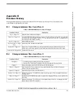
Figure 19-3 / Page 19-5
Corrected the reset value for ANDIS, DIS100, and DIS10 (was 0, is 1).
Figure 19-4 / Page 19-7
Corrected the name of bit 4 (was PHYADD4, is PHYADD3).
Figure 19-5 / Page 19-7
Corrected the reset value for 100DIS and 10DIS (was 0, is 1).
Section 19.3.3.2 / Page 19-11 • Corrected the name of bit 11 (was PDWN, is 10THD).
• Corrected the description of bit 11 (the proper description is found in Revision 2 of the
reference manual).
Figure 19-8 / Page 19-13
Corrected the reset value for bit 11 (was 01, is 0).
Section 19.3.3.4 / Page 19-13 • Corrected the reset value for PHYID (was 0b000000, is 0b000110).
• Corrected the PHYID field description (was “Composed of bits 15:10.”, is “Composed of bits
19:24”).
Table 19-10 / Page 19-14
Added a description of the SELECTORFIELD field.
Section 19.3.3.6 / Page 19-15 • Updated the register figure and field description table to show that bits 12:11 are reserved.
• Added a description of the SELECTORFIELD field.
Section 19.3.3.7 / Page 19-16 Provided a concise name for bits 10:0 (was “Message/Unformatted Code Field [10:0]”, is
CODEFIELD).
Section 19.3.3.9 / Page 19-18 Provided a concise name for bits 10:0 (was “Message/Unformatted Code Field [10:0]”, is
CODEFIELD).
Figure 19-16 / Page 19-20
• Updated the figure to show that the register is read-only.
• Added the following footnote to ANCMODE: “This bit is valid only when ANNC is set.”
Figure 19-17 / Page 19-21
• Corrected the reset value for FEFLTD (was 1, is 0).
• Corrected the reset value for bit 12 (was 1, is 0).
• Corrected the reset value for bit 11 (was 0, is 1).
• Corrected the reset value for JBDE (was 0, is 1).
• Corrected the reset value for POLCORD [was “(1)”, is 0].
Table 19-17 / Page 19-21
• Corrected the name of bit 13 (was MIILBO, is MIILBD).
• Corrected the description of bit 12 (is “Reserved, should be cleared.”)
• Corrected the description of bit 11 (is “Reserved, should be set.”)
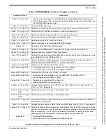
Figure 25-1 / Page 25-1
Corrected signal name (was QSPI_CS[:0], is QSPI_CS[3:0]).
Section 26.2 / Page 26-3
Changed "An internal interrupt request signal notifies the interrupt controller..." to "A request
signal is provided to notify the interrupt controller...".
Table 26-6 / Page 26-9
Changed “DTIN” to “DTnIN” (to maintain consistent signal names throughout chapter).
Section 26.4.5.2 / Page 26-26 Changed "...complete normally without exception processing..." to "...complete normally without
an error termination...".
Section 27.6 / Page 27-12
Changed programming examples from assembly language to pseudocode.
Table 29-1 / Page 29-2
Deleted reference to nonexistent SCMISR register from footnote 2.
Table 31-10 / Page 31-16
• Added the following note to the PBR0[Address] field description:
Note: PBR0[0] should always be loaded with a 0.
• Changed the bit range in the Field column (was 31–1, is 31–0).
Figure 31-8 / Page 31-16
Changed the address of PBR3 (was 0x1C, is 0x1B).
Table 31-22 / Page 31-39
Changed the initial state of the CSR (was 0x0, is 0x0090_0000).
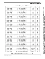
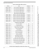
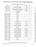
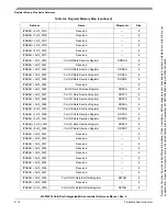
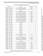
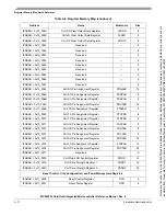
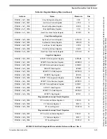
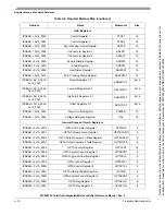
Table 3. MCF52235RM Rev. 3 to Rev. 4 Changes (continued)
Location in Rev. 3
Description
Because
of
an
order
from
the
United
States
International
Trade
Commission,
BGA-packaged
product
lines
and
part
numbers
indicated
here
currently
are
not
available
from
Freescale
for
import
or
sale
in
the
United
States
prior
to
September
2010:MCF52234CVM60,
MCF52235CVM60


