


Pulse-Width Modulation (PWM) Module
Freescale Semiconductor
29-18
MCF52235 ColdFire® Integrated Microcontroller Reference Manual, Rev. 6
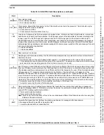
29.3.2.5
Left-Aligned Outputs
The PWM timer provides the choice of two types of outputs: left- or center-aligned. They are selected with
the PWMCAE[CAE
n
] bits. If the CAE
n
bit is cleared, the corresponding PWM output is left-aligned.
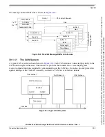
In left-aligned output mode, the 8-bit counter is configured as an up counter only. It compares to two
registers, a duty register and a period register, as shown in the block diagram in
PWM counter matches the duty register, the output flip-flop changes state causing the PWM waveform to
also change state. A match between the PWM counter and the period register resets the counter and the
output flip-flop, as shown in
, as well as performing a load from the double buffer period and
duty register to the associated registers, as described in
. The counter counts from 0 to the
value in the period register minus 1.
NOTE
Changing the PWM output mode from left-aligned to center-aligned output
(or vice versa) while channels are operating can cause irregularities in the
PWM output. It is recommended to program the output mode before
enabling the PWM channel.
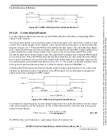
Figure 29-16. PWM Left-Aligned Output Waveform
To calculate the output frequency in left-aligned output mode for a particular channel, take the selected
clock source frequency for the channel (A, B, SA, or SB) and divide it by the value in the period register
for that channel.
Eqn. 29-7
The PWM
n
duty cycle (high time as a percentage of period) is expressed as:
Eqn. 29-8
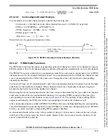
29.3.2.5.1
Left-Aligned Output Example
As an example of a left-aligned output, consider the following case:
Clock source = internal bus clock, where internal bus clock = 40 MHz (25 ns period)
PPOL
n
= 0, PWMPER
n
= 4, PWMDTY
n
= 1
PWM
n
frequency = 40 MHz
÷
4 = 10 MHz
PWM
n
period = 100 ns
The output waveform generated is below:
PWMDTYn
Period = PWMPERn
PPOLn = 0
PPOLn = 1
PWM
n
frequency
Clock (A, B, SA, or SB)
PWMPER
n
----------------------------------------------------------
=
Duty Cycle
1
PWMPOL PPOL
n
[
]
PWMDTY
n
PWMPER
n
-------------------------------
–
–
⎝
⎠
⎛
⎞
100%
×
=
PWMn Duty Cycle
1
1
4
---
–
⎝
⎠
⎛
⎞
100% 75%
=
×
=
Because
of
an
order
from
the
United
States
International
Trade
Commission,
BGA-packaged
product
lines
and
part
numbers
indicated
here
currently
are
not
available
from
Freescale
for
import
or
sale
in
the
United
States
prior
to
September
2010:MCF52234CVM60,
MCF52235CVM60


