


Debug Module
MCF52235 ColdFire® Integrated Microcontroller Reference Manual, Rev. 6
Freescale Semiconductor
31-7
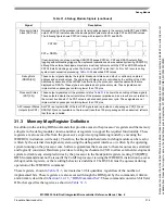
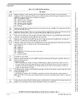
15
MAP
Force processor references in emulator mode.
0 All emulator-mode references are mapped into supervisor code and data spaces.
1 The processor maps all references while in emulator mode to a special address space, TT equals 10,
TM equals 101 or 110. The internal SRAM and caches are disabled.
14
TRC
Force emulation mode on trace exception.
0 The processor enters supervisor mode
1 The processor enters emulator mode when a trace exception occurs
13
EMU
Force emulation mode.
0 Do not force emulator mode
1 The processor begins executing in emulator mode. See
Section 31.4.2.2, “Emulator Mode”
.
12–11
DDC
Debug data control. Controls operand data capture for DDATA, which displays the number of bytes defined by the
operand reference size before the actual data; byte displays 8 bits, word displays 16 bits, and long displays 32
bits (one nibble at a time across multiple PSTCLK clock cycles). See
.
00 No operand data is displayed.
01 Capture all write data.
10 Capture all read data.
11 Capture all read and write data.
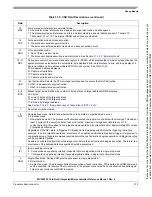
10
UHE
User halt enable. Selects the CPU privilege level required to execute the HALT instruction.
0 HALT is a supervisor-only instruction.
1 HALT is a supervisor/user instruction.
9–8
BTB
Branch target bytes. Defines the number of bytes of branch target address DDATA displays.
00 0 bytes
01 Lower 2 bytes of the target address
10 Lower 3 bytes of the target address
11 Entire 4-byte target address
See
Section 31.4.4.1, “Begin Execution of Taken Branch (PST = 0x5)”
.
7
Reserved, must be cleared.
6
NPL
Non-pipelined mode. Determines whether the core operates in pipelined mode or not.
0 Pipelined mode
1 Non-pipelined mode. The processor effectively executes one instruction at a time with no overlap. This adds at
least 5 cycles to the execution time of each instruction. Given an average execution latency of 1.6
cycles/instruction, throughput in non-pipeline mode would be 6.6 cycles/instruction, approximately 25% or less
of pipelined performance.
Regardless of the NPL state, a triggered PC breakpoint is always reported before the triggering instruction
executes. In normal pipeline operation, occurrence of an address and/or data breakpoint trigger is imprecise. In
non-pipeline mode, triggers are always reported before the next instruction begins execution and trigger reporting
can be considered precise.
An address or data breakpoint should always occur before the next instruction begins execution. Therefore, the
occurrence of the address/data breakpoints should be guaranteed.
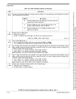
5
IPI
Ignore pending interrupts.
0 Core services any pending interrupt requests that were signalled while in single-step mode.
1 Core ignores any pending interrupt requests signalled while in single-instruction-step mode.
4
SSM
Single-Step Mode. Setting SSM puts the processor in single-step mode.
0 Normal mode.
1 Single-step mode. The processor halts after execution of each instruction. While halted, any BDM command
can be executed. On receipt of the
GO
command, the processor executes the next instruction and halts again.
This process continues until SSM is cleared.
Table 31-5. CSR Field Descriptions (continued)
Field
Description
Because
of
an
order
from
the
United
States
International
Trade
Commission,
BGA-packaged
product
lines
and
part
numbers
indicated
here
currently
are
not
available
from
Freescale
for
import
or
sale
in
the
United
States
prior
to
September
2010:MCF52234CVM60,
MCF52235CVM60


