


Fast Ethernet Controller (FEC)
MCF52235 ColdFire® Integrated Microcontroller Reference Manual, Rev. 6
Freescale Semiconductor
18-47
18.6
Buffer Descriptors
This section provides a description of the operation of the driver/DMA via the buffer descriptors. It is
followed by a detailed description of the receive and transmit descriptor fields.
18.6.1
Driver/DMA Operation with Buffer Descriptors
The data for the FEC frames must reside in memory external to the FEC. The data for a frame is placed in
one or more buffers. Associated with each buffer is a buffer descriptor (BD) which contains a starting
address (pointer), data length, and status/control information (which contains the current state for the
buffer). To permit maximum user flexibility, the BDs are also located in external memory and are read in
by the FEC DMA engine.
Software produces buffers by allocating/initializing memory and initializing buffer descriptors. Setting the
RxBD[E] or TxBD[R] bit produces the buffer. Software writing to the TDAR or RDAR tells the FEC that
a buffer has been placed in external memory for the transmit or receive data traffic, respectively. The
hardware reads the BDs and consumes the buffers after they have been produced. After the data DMA is
complete and the buffer descriptor status bits have been written by the DMA engine, the RxBD[E] or
TxBD[R] bit is cleared by hardware to signal the buffer has been consumed. Software may poll the BDs
to detect when the buffers have been consumed or may rely on the buffer/frame interrupts. These buffers
may then be processed by the driver and returned to the free list.
The ECR[ETHER_EN] signal operates as a reset to the BD/DMA logic. When ECR[ETHER_EN] is
deasserted the DMA engine BD pointers are reset to point to the starting transmit and receive BDs. The
buffer descriptors are not initialized by hardware during reset. At least one transmit and receive buffer
descriptor must be initialized by software before the ECR[ETHER_EN] bit is set.
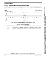
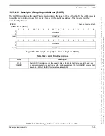
The buffer descriptors operate as two separate rings. ERDSR defines the starting address for receive BDs
and ETDSR defines the starting address for transmit BDs. The last buffer descriptor in each ring is defined
by the Wrap (W) bit. When set, W indicates that the next descriptor in the ring is at the location pointed to
by ERDSR and ETDSR for the receive and transmit rings, respectively. Buffer descriptor rings must start
on a 32-bit boundary; however, it is recommended they are made 128-bit aligned.
18.6.1.1
Driver/DMA Operation with Transmit BDs
Typically a transmit frame is divided between multiple buffers. An example is to have an application
payload in one buffer, TCP header in a 2nd buffer, IP header in a 3rd buffer, Ethernet/IEEE 802.3 header
in a 4th buffer. The Ethernet MAC does not prefix the Ethernet header (destination address, source address,
length/type field(s)), so this must be provided by the driver in one of the transmit buffers. The Ethernet
MAC can append the Ethernet CRC to the frame. Whether the CRC is appended by the MAC or by the
driver is determined by the TC bit in the transmit BD which must be set by the driver.
The driver (TxBD software producer) should set up Tx BDs in such a way that a complete transmit frame
is given to the hardware at once. If a transmit frame consists of three buffers, the BDs should be initialized
with pointer, length and control (W, L, TC, ABC) and then the TxBD[R] bits should be set equal to 1 in
reverse order (3rd, 2nd, 1st BD) to ensure that the complete frame is ready in memory before the DMA
begins. If the TxBDs are set up in order, the DMA Controller could DMA the first BD before the 2nd was
made available, potentially causing a transmit FIFO underrun.
Because
of
an
order
from
the
United
States
International
Trade
Commission,
BGA-packaged
product
lines
and
part
numbers
indicated
here
currently
are
not
available
from
Freescale
for
import
or
sale
in
the
United
States
prior
to
September
2010:MCF52234CVM60,
MCF52235CVM60


