281
Chapter 27 Solder Circuit Board
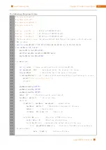
The following is the program code:
1
2
3
4
5
6
7
8
9
10
11
12
13
14
15
16
17
18
19
20
21
22
23
24
25
26
27
28
29
30
31
32
33
34
35
36
37
38
39
40
41
42
43
#include <wiringPi.h>
#include <stdio.h>
#include <wiringShift.h>
#include <unistd.h>
#define dataPin 0
//DS Pin of 74HC595(Pin14)
#define latchPin 2
//ST_CP Pin of 74HC595(Pin12)
#define clockPin 3
//SH_CP Pin of 74HC595(Pin11)
//Define an array to save the pulse width of LED. Output the signal to the 8 adjacent
LEDs in order.
const
int
pluseWidth
[]={
0
,
0
,
0
,
0
,
0
,
0
,
0
,
0
,
64
,
32
,
16
,
8
,
4
,
2
,
1
,
0
,
0
,
0
,
0
,
0
,
0
,
0
,
0
};
void
outData
(
int8_t
data
){
digitalWrite
(
latchPin
,
LOW
);
shiftOut
(
dataPin
,
clockPin
,
LSBFIRST
,
data
);
digitalWrite
(
latchPin
,
HIGH
);
}
int
main
(
void
)
{
int
i
,
j
,
index
;
//index:current position in array pluseWidth
int
moveSpeed
=
100
;
//move speed delay, the greater, the slower
long
lastMove
;
//Record the last time point of the move
if
(
wiringPiSetup
()
==
-
1
){
//when initialize wiring failed, print message to screen
printf
(
"setup wiringPi failed !"
);
return
1
;
}
pinMode
(
dataPin
,
OUTPUT
);
pinMode
(
latchPin
,
OUTPUT
);
pinMode
(
clockPin
,
OUTPUT
);
index
=
0
;
//Starting from the array index 0
lastMove
=
millis
();
//the start time
while
(
1
){
if
(
millis
()
-
lastMove
>
moveSpeed
)
{
//speed control
lastMove
=
millis
();
//Record the time point of the move
index
++;
//move to next
if
(
index
>
15
)
index
=
0
;
//index to 0
}
for
(
i
=
0
;
i
<
64
;
i
++){
//The cycle of PWM is 64 cycles
int8_t
data
=
0
;
//This loop of output data
for
(
j
=
0
;
j
<
8
;
j
++){
//Calculate the output state of this loop
if
(
i
<
pluseWidth
[
index
+
j
]){
//Calculate the LED state according to
the pulse width
data
|=
0x01
<<
j
;
//Calculate the data
}
Содержание Ultimate Starter Kit
Страница 1: ...Free your innovation Freenove is an open source electronics platform www freenove com ...
Страница 116: ...Chapter 9 Potentiometer RGBLED 116 www freenove com support freenove com Circuit Schematic diagram ...
Страница 117: ...117 Chapter 9 Potentiometer RGBLED www freenove com support freenove com Hardware connection ...
Страница 136: ...Chapter 12 Joystick 136 www freenove com support freenove com Circuit Schematic diagram Hardware connection ...
Страница 155: ...155 Chapter 14 Relay Motor www freenove com support freenove com Hardware connection OFF 3 3V ...
Страница 173: ...173 Chapter 16 Stepping Motor www freenove com support freenove com Hardware connection ...
Страница 182: ...Chapter 17 74HC595 LEDBar Graph 182 www freenove com support freenove com Circuit Schematic diagram Hardware connection ...
Страница 197: ...197 Chapter 18 74HC595 7 segment display www freenove com support freenove com Circuit Schematic diagram ...
Страница 198: ...Chapter 18 74HC595 7 segment display 198 www freenove com support freenove com Hardware connection ...
Страница 239: ...239 Chapter 22 Matrix Keypad www freenove com support freenove com Circuit Schematic diagram ...
Страница 240: ...Chapter 22 Matrix Keypad 240 www freenove com support freenove com Hardware connection ...
Страница 270: ...Chapter 26 WebIOPi IOT 270 www freenove com support freenove com Circuit Schematic diagram Hardware connection ...

