77
Chapter 4 Analog & PWM
In practical application, we often use binary signal as digital signal, that is 0 and 1. The binary signal only has
two forms (0 or 1), so it has strong stability. And digital signal and analog signal can be converted to each
other.
PWM
PWM, namely Pulse-Width Modulation, is a very effective technique for using digital signals to control analog
circuits. The common processors can not directly output analog signals. PWM technology make it very
convenient to achieve this purpose.
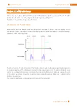
PWM technology uses digital pins to send certain frequency of square waves, that is, the output of high level
and low level that last for a while alternately. The total time for each set of high level and low level is generally
fixed, which is called period (the reciprocal of the period is frequency). The time of high level outputting is
generally called pulse width, and the percentage of pulse width is called duty cycle.
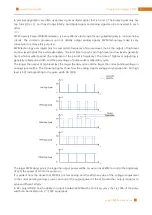
The longer the output of high level last, the larger the duty cycle and the larger the corresponding voltage in
analog signal will be. The following figures show how the analog signals voltage vary between 0V-5V (high
level is 5V) corresponding to the pulse width 0%-100%:
The larger PWM duty cycle is, the lager the output power will be. So we can use PWM to control the brightness
of LED, the speed of DC motor and so on.
It is evident from the above that PWM is not real analog, and the effective value of the voltage is equivalent
to the corresponding analog. so, we can control the output power of the LED and other output modules to
achieve different effects.
In RPi, only GPIO18 has the ability to output hardware PWM with a 10-bit accuracy, that is, 100% of the pulse
width can be divided into 2
10
=1024 equal parts.
Содержание Ultimate Starter Kit
Страница 1: ...Free your innovation Freenove is an open source electronics platform www freenove com ...
Страница 116: ...Chapter 9 Potentiometer RGBLED 116 www freenove com support freenove com Circuit Schematic diagram ...
Страница 117: ...117 Chapter 9 Potentiometer RGBLED www freenove com support freenove com Hardware connection ...
Страница 136: ...Chapter 12 Joystick 136 www freenove com support freenove com Circuit Schematic diagram Hardware connection ...
Страница 155: ...155 Chapter 14 Relay Motor www freenove com support freenove com Hardware connection OFF 3 3V ...
Страница 173: ...173 Chapter 16 Stepping Motor www freenove com support freenove com Hardware connection ...
Страница 182: ...Chapter 17 74HC595 LEDBar Graph 182 www freenove com support freenove com Circuit Schematic diagram Hardware connection ...
Страница 197: ...197 Chapter 18 74HC595 7 segment display www freenove com support freenove com Circuit Schematic diagram ...
Страница 198: ...Chapter 18 74HC595 7 segment display 198 www freenove com support freenove com Hardware connection ...
Страница 239: ...239 Chapter 22 Matrix Keypad www freenove com support freenove com Circuit Schematic diagram ...
Страница 240: ...Chapter 22 Matrix Keypad 240 www freenove com support freenove com Hardware connection ...
Страница 270: ...Chapter 26 WebIOPi IOT 270 www freenove com support freenove com Circuit Schematic diagram Hardware connection ...

