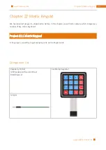
Chapter 22 Matrix Keypad
242
14
15
16
17
18
19
20
21
22
23
24
25
26
27
28
29
30
31
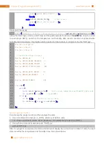
Keypad keypad
=
Keypad
(
makeKeymap
(
keys
),
rowPins
,
colPins
,
ROWS
,
COLS
) ;
int
main
( ){
printf
(
"Program is starting ... \n"
) ;
i f
(
wiringPiSetup
()
= =
-
1
) {
//when initialize wiring failed, print message to screen
printf
(
"setup wiringPi failed !"
) ;
r e turn
1
;
}
char
key
=
0
;
keypad
.
setDebounceTime
(
50
);
w h ile
(
1
){
key
=
keypad
.
getKey
();
//get the state of keys
i f
(
key
) {
//if a key is pressed, print out its key code
printf
(
"You Pressed key : %c \n"
,
key
);
}
}
r e turn
1
;
}
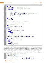
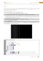
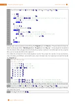
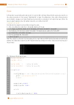
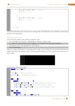
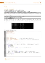
In this project code, we use two custom library file "
Keypad
.hpp" and "
Key
.hpp". They are located in the same
directory with program files "
MatrixKeypad
.cpp", "
Keypad
.cpp" and "
Key
.cpp". Library Keypad is transplanted
from the Arduino library Keypad. And this library file provides a method to read the keyboard. By using this
library, we can easily read the matrix keyboard.
First, define the information of the matrix keyboard used in this project: the number of rows and columns,
code of each key and GPIO pin connected to each column and each row. It is necessary to include the header
file "
Keypad
.hpp".
#include "Keypad.hpp"
#include <stdio.h>
const
byte ROWS
=
4
;
//four rows
const
byte COLS
=
4
;
//four columns
char
keys
[
ROWS
][
COLS
]
=
{
//key code
{
'1'
,
'2'
,
'3'
,
'A'
},
{
'4'
,
'5'
,
'6'
,
'B'
},
{
'7'
,
'8'
,
'9'
,
'C'
},
{
'*'
,
'0'
,
'#'
,
'D'
}
} ;
byte rowPins
[
ROWS
]
=
{
1
,
4
,
5
,
6
} ;
//connect to the row pinouts of the keypad
byte colPins
[
COLS
]
=
{
12
,
3
,
2
,
0
} ;
//connect to the column pinouts of the keypad
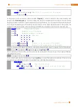
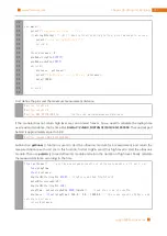
And then, based on the above information, instantiate a Keypad class object to operate the matrix keyboard.
Keypad keypad
=
Keypad
(
makeKeymap
(
keys
),
rowPins
,
colPins
,
ROWS
,
COLS
) ;
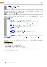
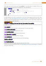
Set the debounce time to 50ms, and this value can be set based on the actual use of the keyboard flexibly,
with default time 10ms.
keypad
.
setDebounceTime
(
50
);
Содержание Ultimate Starter Kit
Страница 1: ...Free your innovation Freenove is an open source electronics platform www freenove com ...
Страница 116: ...Chapter 9 Potentiometer RGBLED 116 www freenove com support freenove com Circuit Schematic diagram ...
Страница 117: ...117 Chapter 9 Potentiometer RGBLED www freenove com support freenove com Hardware connection ...
Страница 136: ...Chapter 12 Joystick 136 www freenove com support freenove com Circuit Schematic diagram Hardware connection ...
Страница 155: ...155 Chapter 14 Relay Motor www freenove com support freenove com Hardware connection OFF 3 3V ...
Страница 173: ...173 Chapter 16 Stepping Motor www freenove com support freenove com Hardware connection ...
Страница 182: ...Chapter 17 74HC595 LEDBar Graph 182 www freenove com support freenove com Circuit Schematic diagram Hardware connection ...
Страница 197: ...197 Chapter 18 74HC595 7 segment display www freenove com support freenove com Circuit Schematic diagram ...
Страница 198: ...Chapter 18 74HC595 7 segment display 198 www freenove com support freenove com Hardware connection ...
Страница 239: ...239 Chapter 22 Matrix Keypad www freenove com support freenove com Circuit Schematic diagram ...
Страница 240: ...Chapter 22 Matrix Keypad 240 www freenove com support freenove com Hardware connection ...
Страница 270: ...Chapter 26 WebIOPi IOT 270 www freenove com support freenove com Circuit Schematic diagram Hardware connection ...

