81
Chapter 4 Analog & PWM
28
29
30
31
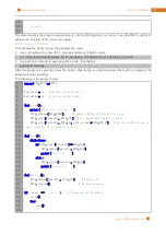
loop
( )
e x cept
KeyboardInterrupt
:
# When 'Ctrl+C' is pressed, the subprogram destroy() will
be executed.
destroy
()
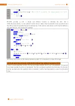
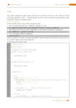
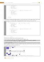
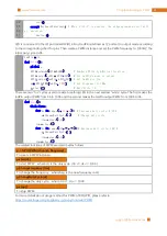
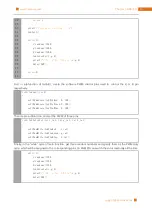
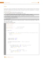
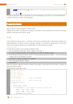
LED is connected to the IO port called GPIO18. And LedPin is defined as 12 and set to output mode according
to the corresponding chart for pins. Then create a PWM instance and set the PWM frequency to 1000HZ, the
initial duty cycle to 0%.
LedPin
=
12
d e f
setup
( ):
g l obal
p
GPIO
.
setmode
(
GPIO
.
BOARD
)
# Numbers GPIOs by physical location
GPIO
.
setup
(
LedPin
,
GPIO
.
OUT
)
# Set LedPin's mode is output
GPIO
.
output
(
LedPin
,
GPIO
.
LOW
)
# Set LedPin to low
p
=
GPIO
.
PWM
(
LedPin
,
1000
)
# Set Frequency to 1KHz
p
.
start
(
0
)
# Duty Cycle = 0
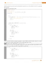
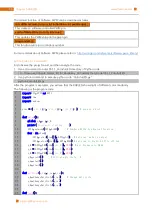
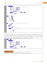
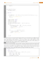
There are two “for” cycles used to realize breathing LED in the next endless “while” cycle. The first makes the
ledPin output PWM from 0% to 100% and the second makes the ledPin output PWM from 100% to 0%.
d e f
loop
( ):
w h ile
T r ue
:
f o r
dc
i n
range
(
0
,
101
,
1
) :
# Increase duty cycle: 0~100
p
.
ChangeDutyCycle
(
dc
)
# Change duty cycle
time
.
sleep
(
0.01
)
time
.
sleep
(
1
)
f o r
dc
i n
range
(
100
,
-
1
,
-
1
):
# Decrease duty cycle: 100~0
p
.
ChangeDutyCycle
(
dc
)
time
.
sleep
(
0.01
)
time
.
sleep
(
1
)
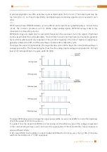
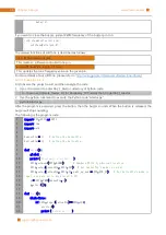
The related functions of PWM are described as follows:
p = GPIO.PWM(channel, frequency)
To create a PWM instance:
p.start(dc)
To start PWM:,where dc is the duty cycle (0.0 <= dc <= 100.0)
p.ChangeFrequency(freq)
To change the frequency,where freq is the new frequency in Hz
p.ChangeDutyCycle(dc)
To change the duty cycle,where 0.0 <= dc <= 100.0
p.stop()
To stop PWM.
For more details about usage method for PWM of RPi.GPIO, please refer to:
https://sourceforge.net/p/raspberry-gpio-python/wiki/PWM/
Содержание Ultimate Starter Kit
Страница 1: ...Free your innovation Freenove is an open source electronics platform www freenove com ...
Страница 116: ...Chapter 9 Potentiometer RGBLED 116 www freenove com support freenove com Circuit Schematic diagram ...
Страница 117: ...117 Chapter 9 Potentiometer RGBLED www freenove com support freenove com Hardware connection ...
Страница 136: ...Chapter 12 Joystick 136 www freenove com support freenove com Circuit Schematic diagram Hardware connection ...
Страница 155: ...155 Chapter 14 Relay Motor www freenove com support freenove com Hardware connection OFF 3 3V ...
Страница 173: ...173 Chapter 16 Stepping Motor www freenove com support freenove com Hardware connection ...
Страница 182: ...Chapter 17 74HC595 LEDBar Graph 182 www freenove com support freenove com Circuit Schematic diagram Hardware connection ...
Страница 197: ...197 Chapter 18 74HC595 7 segment display www freenove com support freenove com Circuit Schematic diagram ...
Страница 198: ...Chapter 18 74HC595 7 segment display 198 www freenove com support freenove com Hardware connection ...
Страница 239: ...239 Chapter 22 Matrix Keypad www freenove com support freenove com Circuit Schematic diagram ...
Страница 240: ...Chapter 22 Matrix Keypad 240 www freenove com support freenove com Hardware connection ...
Страница 270: ...Chapter 26 WebIOPi IOT 270 www freenove com support freenove com Circuit Schematic diagram Hardware connection ...


