background image


149 

Chapter 13 Motor & Driver 


  www.freenove.com 

[email protected]  █ 

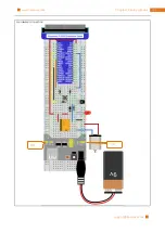
Python Code 13.1.1 Motor 

First observe the project result, and then analyze the code. 
1.


Use cd command to enter 13.1.1_Motor  directory of Python code. 
cd ~/Freenove_Ultimate_Starter_Kit_for_Raspberry_Pi/Code/Python_Code/13.1.1_Motor 

2.


Use python command to execute  python code “Motor.py”.   
python Motor.py 

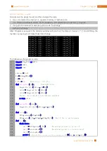
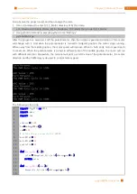
After the program is executed,  shift the potentiometer,  then the rotation  speed and direction  of the motor 
will change  with it.  And when the  potentiometer  is  turned to midpoint  position, the  motor stops running. 
When away from the middle position, the motor speed will increase. When to both ends, motor speed reach 
to maximum. When the potentiometer  is  turned to different side of the middle position, the motor will  run 
with different  direction.  Meanwhile,  the terminal  will print out  ADC value of the  potentiometer,  the  motor 
direction and the PWM duty cycle used to control motor speed. 


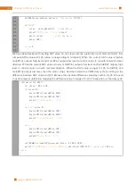
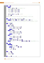
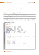
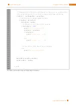
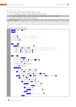
The following is the code: 


10 

11 
12 

13 

14 

15 

16 
17 

18 

19 

i m port

 RPi

.

GPIO 

a s

 GPIO 

i m port

 smbus 

i m port

 time 


address 

=


0x48


bus

=

smbus

.

SMBus

(

1

)


cmd

=

0x40


# define the pin connected to L293D 


motoRPin1 

=


13


motoRPin2 

=


11


enablePin 

=


15


d e f


analogRead

(

chn

):


    value 

=

 bus

.

read_byte_data

(

address

,

cmd

+

chn

)


r e turn

 value 


d e f


analogWrite

(

value

):


    bus

.

write_byte_data

(

address

,

cmd

,

value

)


Содержание Ultimate Starter Kit

Страница 1: ...Free your innovation Freenove is an open source electronics platform www freenove com ...

Страница 2: ...parts of this product while they are operating Some parts of this product may become warm to touch when used in certain circuit designs This is normal Improper operation may cause excessively overheating Using this product not in accordance with the specification may cause damage to the product About Freenove is an open source electronics platform Freenove is committed to helping customer quickly ...

Страница 3: ...ree and quick technical support including but not limited to Quality problems of products Problems in using products Questions for learning and technology Opinions and suggestions Ideas and thoughts Please send email to support freenove com On working day we usually reply to you within 24 hours Copyright Freenove reserves all rights to this book No copies or plagiarizations are allowed for the pur...

Страница 4: ...all WiringPi 35 Obtain the Project Code 36 Python2 Python3 37 Code Editor 39 GPIO 44 GPIO Extension Board 48 Breadboard Power Module 49 Next 50 Chapter 1 LED 51 Project 1 1 Blink 51 Chapter 2 Button LED 59 Project 2 1 Button LED 59 Project 2 2 MINI table lamp 65 Chapter 3 LEDBar Graph 71 Project 3 1 Flowing Water Light 71 Chapter 4 Analog PWM 76 Project 4 1 Breathing LED 76 Chapter 5 RGBLED 82 Pro...

Страница 5: ...1 1 Thermometer 128 Chapter 12 Joystick 134 Project 12 1 Joystick 134 Chapter 13 Motor Driver 141 Project 13 1 Control Motor with Potentiometer 141 Chapter 14 Relay Motor 152 Project 14 1 1 Relay Motor 152 Chapter 15 Servo 160 Project 15 1 Servo Sweep 160 Chapter 16 Stepping Motor 169 Project 16 1 Stepping Motor 169 Chapter 17 74HC595 LEDBar Graph 180 Project 17 1 Flowing Water Light 180 Chapter 1...

Страница 6: ...Keypad 237 Chapter 23 Infrared Motion Sensor 247 Project 23 1 Sense LED 247 Chapter 24 Ultrasonic Ranging 253 Project 24 1 Ultrasonic Ranging 253 Chapter 25 Attitude Sensor MPU6050 261 Project 25 1 Read MPU6050 261 Chapter 26 WebIOPi IOT 269 Project 26 1 Remote LED 269 Chapter 27 Solder Circuit Board 274 Project 27 1 Solder a Buzzer 274 Project 27 2 Solder a Flowing Water Light 278 What s next 286...

Страница 7: ...can also combine the advantages of them to make something creative Usually a Raspberry Pi project consists of code and circuit If you are familiar with computer language and very interested in the electronic module Then this tutorial is very suitable for you It will from easy to difficult explain the Raspberry Pi programming knowledge the use of various types of electronic components and sensor mo...

Страница 8: ... and GPIO as a microcomputer can be running in command line mode and desktop system mode Additionally it is easy to operate just like Arduino and you can even directly operate the GPIO of CPU So far Raspberry Pi has developed to the third generation Changes in versions are accompanied by increase and upgrades in hardware A type and B type the first generation of products have been stopped due to v...

Страница 9: ...Pi www freenove com support freenove com Practicality picture of Raspberry Pi 3 Model B Model diagram of Raspberry Pi 3 Model B Practicality picture of Raspberry Pi 2 Model B Model diagram of Raspberry Pi 2 Model B ...

Страница 10: ...Raspberry Pi 10 www freenove com support freenove com Practicality picture of Raspberry Pi 1 Model B Model diagram of Raspberry Pi 1 Model B ...

Страница 11: ...Pi www freenove com support freenove com Practicality picture of Raspberry Pi 3 Model A Model diagram of Raspberry Pi 3 Model A Practicality picture of Raspberry Pi 1 Model A Model diagram of Raspberry Pi 1 Model A ...

Страница 12: ...erry Pi 12 www freenove com support freenove com Practicality picture of Raspberry Pi Zero W Model diagram of Raspberry Pi Zero W Practicality picture of Raspberry Pi Zero Model diagram of Raspberry Pi Zero ...

Страница 13: ...hown below Hardware interface diagram of RPi 3A A is shown below GPIO Connector Display Connector Power Connector HDMI Connector Camera Connector Audio Connector Ethernet Connector USB Connector GPIO Connector Display Connector Power Connector HDMI Connector Camera Connector Audio Connector USB Connector ...

Страница 14: ...Raspberry Pi 14 www freenove com support freenove com Hardware interface diagram of RPi Zero Zero W is shown below GPIO Connector Power Connector HDMI Connector Camera Connector USB Connector ...

Страница 15: ...m Install the System Firstly install a system for your RPi Component List Required Components Any Raspberry Pi 5V 2 5A Power Adapter Different versions of Raspberry Pi have different power requirements Micro USB Cable x1 Micro SD Card TF Card x1 Card Reader x1 ...

Страница 16: ... W 1 2A Limited by PSU board and connector ratings only 150mA Raspberry Pi Zero 1 2A Limited by PSU board and connector ratings only 100mA For more details please refer to https www raspberrypi org help faqs powerReqs In addition RPi also needs a network cable used to connect it to wide area network All of these components are necessary Among them the power supply is required at least 5V 2 5A beca...

Страница 17: ...HUB 4 USB transferring to Ethernet interface or USB Wi Fi receiver For different Raspberry Pi the optional items are slightly different But all of their aims are to convert the special interface to standard interface of standard Raspberry Pi Pi Zero Pi Zero W Pi A Pi 3A Pi B 2B Pi 3B 3B Monitor Yes Yes Yes Yes Yes Yes Mouse Yes Yes Yes Yes Yes Yes Keyboard Yes Yes Yes Yes Yes Yes Mini HDMI to HDMI...

Страница 18: ...tor or you want to use a remote desktop first you need to login to Raspberry Pi through SSH then open the VNC or RDP service So you need the following accessories Pi Zero Pi Zero W Pi A Pi 3A Pi B 2B Pi 3B 3B Micro USB to USB A Receptacles converter wire Micro USB OTG wire Yes Yes No NO USB transferring to Ethernet interface Yes Yes Yes ...

Страница 19: ...s win32diskimager Selecting System Visit RPi official website https www RaspberryPi org click Downloads and choose to download RASPBIAN RASPBIAN supported by RPI is an operating system based on Linux which contains a number of contents required for RPi We recommended RASPBIAN system to beginners All projects in this tutorial are operated under the RASPBIAN system After download extract file with s...

Страница 20: ...Micro SD card into card reader and connect it to USB port of PC Then open Win32 disk imager choose the correct letter of your Micro SD Card here is J open the extracted img file and then click the Write Step1 choose the correct letter Step2 open the extracted img file Step3 Click Write to write the system ...

Страница 21: ... put it into the card slot of RPi Then connect RPi to screen through the HDMI to mouse and keyboard through the USB port to network cable through the network card interface and to the power supply Then your RPi starts initially Later you need to enter the user name and password to login The default user name pi password raspberry Enter and login After login you can enter the following interface No...

Страница 22: ...cation VNC Viewer which corresponds to the VNC interface of Raspberry Pi Each way has its own advantages You can choose either one or two Windows Raspberry Pi Remote Desktop Connection Xrdp VNC Viewer VNC VNC Viewer can not only run under Windows but also under system MAC Linux IOS Android and so on SSH Under previous Raspbian system SSH is opened by default Under the latest version of Raspbian sy...

Страница 23: ...lot of the RPi and turn on the power supply waiting for starting RPi Later enter control terminal of the router to inquiry IP address named raspberry pi For example I have inquired to my RPi IP address and it is 192 168 1 108 Then open Putty enter the address select SSH and then click OPEN as shown below There will appear a security warning at first login Just click YES Step1 enter the IP address ...

Страница 24: ...terface RPi default user name pi the password raspberry When you enter the password there will be no display on the screen This is normal After the correct output press Enter to confirm Then enter the command line of RPi which means that you have successfully login to RPi command line mode ...

Страница 25: ...stall xrdp service on Raspberry Pi Next install a xrdp service an open source remote desktop protocol rdp server for RPi Type the following command then press enter to confirm sudo apt get install xrdp Later the installation starts Enter Y press key Enter to confirm After the installation is completed you can use Windows remote desktop applications to login to your RPi ...

Страница 26: ...e desktop Use WIN R or search function open the remote desktop application mstsc exe under Windows enter the IP address of RPi and then click Connect Later there will be xrdp login screen Enter the user name and password of RPi RPi default user name pi password raspberry and click OK ...

Страница 27: ...27 Install the System www freenove com support freenove com Later you can enter the RPi desktop system Here you have successfully used the remote desktop login to RPi ...

Страница 28: ... freenove com support freenove com VNC Viewer VNC Type the following command And select 5 Interfacing Options P3 VNC Yes OK Finish Here Raspberry Pi may need be restarted and choose ok Then open VNC interface sudo raspi config ...

Страница 29: ...d viewer windows After installation is completed open VNC Viewer And click File New Connection Then the interface is shown below Enter ip address of your Raspberry Pi and fill in a Name And click OK Then on the VNC Viewer panel double click new connection you just created and the following dialog box pops up Enter username pi and Password raspberry And click OK ...

Страница 30: ...oper resolution ratio on set interface of Raspberry Pi sudo raspi config Select 7 Advanced Options A5 Resolution proper resolution ratio set by yourself OK If it needs restart just restart In addition your VNC Viewer window may zoom your Raspberry Pi desktop You can change it On your VNC View control panel click right key And select Properties Options label Scaling Then set proper scaling ...

Страница 31: ...do some preparation work install a GPIO library wiringPi for your RPi Wi Fi Raspberry Pi 3B 3B integrates a Wi Fi adaptor You can use it to connect to your Wi Fi Then you can use the wireless remote desktop to control your RPi This will be helpful for the following work Raspberry Pi of other models can use wireless remote desktop through accessing an external USB wireless card ...

Страница 32: ...r we will do some necessary preparation work start your Pi Raspberry and install some necessary libraries If your Raspberry Pi can be started normally and used normally you can skip this chapter Linux Command Raspbian is based on Linux operation system Now we will introduct some frequently used Linux commands and useage methods First opent terminal All commands are executed in terminal Terminal Br...

Страница 33: ...er content we will often change working path Typing commands under wrong working path will cause error messages And the commands can not continue to be executed There are some frequently used commands and instructions in following table Command instruction ls List information about the FILEs the current directory by default Sort entries alphabetically cd Change directory sudo cmd Excute cmd under ...

Страница 34: ...ey The Tab key can automatically complete the command path you want to type When there are multiple commands paths conforming to the already typed letter pressing Tab key once won t have any result And pressing Tab key again will list all the eligible options This command path will be directly completed when there is only one eligible option As shown below under the directory enter the Documents d...

Страница 35: ...lation For command with many lines execute them line by line Enter the following command in the terminal to obtain WiringPi using git sudo apt get update sudo apt get upgrade git clone git git drogon net wiringPi sudo command It indicates that the command is executed by root user After the cloning operation is completed go to the wiring folder and update the latest WiringPi cd wiringPi git pull or...

Страница 36: ...ithub com freenove Freenove_Ultimate_Starter_Kit_for_Raspberry_Pi After the download is completed a new folder Freenove_Ultimate_Starter_Kit_for_Raspberry_Pi is generated which contains all the tutorials and code If you think the folder name is too long You can rename it by following command mv Freenove_Ultimate_Starter_Kit_for_Raspberry_Pi xxx Among them xxx represents the new folder name If you ...

Страница 37: ...2 7 are transition versions to python3 So you can also use Python2 6 and 2 7 to execute some Python3 code You can type python2 and python3 respectively to check if python has been installed Press Ctrl Z to exit Type python and the terminal shows that it links to python2 If you want to set Python3 as default Python actuators please follow the steps below 1 Enter directory usr bin cd usr bin 2 Delet...

Страница 38: ...and to enter 00 0 0_Hello directory of Python code cd Freenove_Ultimate_Starter_Kit_for_Raspberry_Pi Code Python_Code 00 0 0_Hello 2 Use python2 command to execute python code Hello py python2 Hello py Use Python3 to execute the code under same directory 3 Use python3 command to execute python code Hello py python3 Hello py As you can see we get same results Because the code for our kit supports P...

Страница 39: ... which is recommended for begainer We will use the three editors to open an example code Hello c respectively First we will show how use vi and nano editor First use cd command to enter the sample code folder cd cd Freenove_Ultimate_Starter_Kit_for_Raspberry_Pi Code C_Code 00 0 0_Hello Use the vi editor to open the file Hello c then press q and Enter to exit vi Hello c As is shown below Use the na...

Страница 40: ...ve com As is shown below Use the following command to compile the code to generate the executable file Hello gcc Hello c o Hello Use the following command to run the executable file Hello sudo Hello After the execution Hello World is printed out in terminal ...

Страница 41: ...command to open the Geany in the sample file Hello c file directory path geany Hello c Or find and open Geany directly in the desktop main menu and then click File Open to open the Hello c Or drag Hello c to Geany directly If you want creat a new code click File New File Save as name c or name py Then write the code ...

Страница 42: ...port freenove com Generates an executable file by clicking menu bar Build Build then execute the generated file by clicking menu bar Build Execute After the execution there will be a terminal printing out the characters Hello World as shown below ...

Страница 43: ...you will need change the compiler command here As is shown below Summary Here we have introduced three code editors There also many other good code editors and you can choose any one you like In later projects about the entry path and the compiler execute commands we will operate the contents in the terminal as examples We won t emphasize the code editing process but will explain the contents of t...

Страница 44: ...re 3 different ways to refer to them GPIO numbering physical numbering WiringPi GPIO Numbering BCM GPIO Numbering Raspberry Pi CPU use BCM2835 BCM2836 BCM2837of Broadcom GPIO pin number is set by chip manufacturer These are the GPIO pins as that computer recognizes The numbers don t make any sense to humans They jump all over the place so there is no easy way to remember them You will need a print...

Страница 45: ...ion www freenove com support freenove com PHYSICAL Numbering Another way to refer to the pins is by simply counting across and down from pin 1 at the top left nearest to the SD card This is physical numbering as shown below ...

Страница 46: ...numbers RPi GPIO serial number of the WiringPi was renumbered Here we have three kinds of GPIO number mode based on the number of BCM chip based on the physical sequence number and based on wiringPi The correspondence between these three GPIO numbers is shown below For more details please refer to https projects drogon net raspberry pi wiringpi pins ...

Страница 47: ...hapter 0 Preparation www freenove com support freenove com You can also use the following command to view their correspondence gpio readall For more details about wiringPi please refer to http wiringpi com ...

Страница 48: ...nt to extend all IO ports of RPi to the bread board directly The GPIO sequence on Extension Board is identical to the GPIO sequence of RPi Since the GPIO of different versions of RPi is different the corresponding extensions board are also different For example a GPIO extensions board with 40 pins is connected to RPi as follows Practicality picture of connection ...

Страница 49: ...er Module is an independent board which can provide independent 5V or 3 3V power for bread board when used to build the circuit and it can avoid excessive load power damaging RPi power The schematic diagram of the Breadboard Power Module is shown below Power Jack Power Switch Output voltage selection Output port for power Output voltage selection Output port for power USB Output Port Power Light ...

Страница 50: ... Breadboard Power Module and Breadboard is shown below Next Here all preliminary preparations have been completed Next we will combine the RPi and electronic components to do a series of projects from easy to difficult and focus on explaining the relevant knowledge of electronic circuit ...

Страница 51: ...This chapter is the starting point of the journey to explore RPi electronic projects Let s start with simple Blink Project 1 1 Blink In this project let s try to use RPi to control LED blinking Component List Raspberry Pi 3B x1 GPIO Extension Board Wire x1 BreadBoard x1 ...

Страница 52: ...ly if the voltage of its positive electrode is higher than its negative electrode The LED can not be directly connected to power supply which can damage component A resistor with certain resistance must be connected in series in the circuit of LED Resistor The unit of resistance R is ohm Ω 1mΩ 1000kΩ 1kΩ 1000Ω Resistor is an electrical component that limits or regulates the flow of current in an e...

Страница 53: ...he following diagram the current through R1 is I U R 5V 10kΩ 0 0005A 0 5mA Do not connect the two poles of power supply with low resistance which will make the current too high to damage electronic components And resistor has no poles Breadboard Take a short breadboard as an example to introduce its feature as below The left picture shows the way of connection of pins The right picture shows the p...

Страница 54: ...Shield In addition short circuit especially 5V and GND 3 3V and GND should be avoid because short circuit may cause abnormal circuit work or even damage to RPi Schematic diagram Hardware connection Because Numbering of GPIO Extension Shield is the same as RPi GPIO later Hardware connection diagram will only show the part of breadboard and GPIO Extension Shield Note Do NOT rotate Raspberry Pi to ch...

Страница 55: ...tarter_Kit_for_Raspberry_Pi Code C_Code 01 1 1_Blink 2 Use the following command to compile the code Blink c and generate executable file Blink l of lwiringPi is low case of L gcc Blink c o Blink lwiringPi 3 Then run the generated file blink sudo Blink Now LED start blink You can press Ctrl C to end the program The following is the program code 1 2 3 4 5 6 7 8 9 10 11 12 13 14 15 16 17 18 include ...

Страница 56: ...cycle unless it is ended outside In this cycle use digitalWrite ledPin HIGH to make ledPin output high level then LED is turned on After a period of time delay use digitalWrite ledPin LOW to make ledPin output low level then LED is turned off which is followed by a delay Repeat the cycle then LED will start blinking pinMode ledPin OUTPUT while 1 digitalWrite ledPin HIGH led is turned on printf led...

Страница 57: ...Pin 11 RPI Board pin11 def setup GPIO setmode GPIO BOARD Numbers GPIOs by physical location GPIO setup ledPin GPIO OUT Set ledPin s mode is output GPIO output ledPin GPIO LOW Set ledPin low to off led print using pin d ledPin def loop while True GPIO output ledPin GPIO HIGH led on print led on time sleep 1 delay 1 second GPIO output ledPin GPIO LOW led off print led off time sleep 1 def destroy GP...

Страница 58: ...irectly the program will be terminated too but destroy function will not be executed So GPIO resources won t be released in the warning messagemay appear next time you use GPIO So it is not a good habit to close the program terminal directly def destroy GPIO output ledPin GPIO LOW led is turned off GPIO cleanup Release resource About RPi GPIO RPi GPIO This is a Python module to control the GPIO on...

Страница 59: ...instructions and then make the appropriate action such as lights the LED make a buzzer beep and so on Next we will build a simple control system to control LED through a button Project 2 1 Button LED In the project we will control the LED state through a button When the button is pressed LED will be turn on and when it is released LED will be turn off Component List Raspberry Pi 3B x1 GPIO Extensi...

Страница 60: ...com Component knowledge Push button Push button has 4 pins Two pins on the left is connected and the right is similar as the left which is shown in the below When the push button is pressed the circuit is turned on Circuit Schematic diagram Hardware connection ...

Страница 61: ...ontinues to print out the characters led off Press the button then LED is turned on and then terminal window prints out the led on Release the button then LED is turned off and then terminal window prints out the led off You can press Ctrl C to terminate the program The following is the program code 1 2 3 4 5 6 7 8 9 10 11 12 13 14 15 16 17 18 19 20 21 22 23 24 25 26 27 include wiringPi h include ...

Страница 62: ... In the while cycle of main function use digitalRead buttonPin to determine the state of Button When the button is pressed the function returns low level the result of if is true and then turn on LED Or turn off LED if digitalRead buttonPin LOW button has pressed down digitalWrite ledPin HIGH led on printf led on n else button has released digitalWrite ledPin LOW led off printf led off n About dig...

Страница 63: ... The following is the program code 1 2 3 4 5 6 7 8 9 10 11 12 13 14 15 16 17 18 19 20 21 22 23 24 25 26 27 28 29 30 31 32 import RPi GPIO as GPIO ledPin 11 define the ledPin buttonPin 12 define the buttonPin def setup print Program is starting GPIO setmode GPIO BOARD Numbers GPIOs by physical location GPIO setup ledPin GPIO OUT Set ledPin s mode is output GPIO setup buttonPin GPIO IN pull_up_down ...

Страница 64: ... output GPIO setup buttonPin GPIO IN pull_up_down GPIO PUD_UP Set buttonPin s mode is input and pull up to high level 3 3V In the loop function while dead circulation continue to judge whether the key is pressed When the button is pressed the GPIO input buttonPin will return low level then the result of if is true ledPin outputs high level LED is turned on Or LED will be turned off def loop while ...

Страница 65: ...uous buffeting before it becomes another state And the releasing situation is similar with that process Therefore if we directly detect the state of Push Button there may be multiple pressing and releasing action in one pressing process The buffeting will mislead the high speed operation of the microcontroller to cause a lot of false judgments So we need to eliminate the impact of buffeting Our so...

Страница 66: ...e Button once then LED is turned on Press the Button another time then LED is turned off 1 2 3 4 5 6 7 8 9 10 11 12 13 14 15 16 17 18 19 20 21 22 23 24 25 26 27 28 include wiringPi h include stdio h define ledPin 0 define the ledPin define buttonPin 1 define the buttonPin int ledState LOW store the State of led int buttonState HIGH store the State of button int lastbuttonState HIGH store the lastS...

Страница 67: ...reading return 0 This code focuses on eliminating the buffeting of button We define several variables to save the state of LED and button Then read the button state in while constantly and determine whether the state has changed If it is record this time point reading digitalRead buttonPin read the current state of button if reading lastbuttonState lastChangeTime millis millis Returns the number o...

Страница 68: ...on And if it is low level the changing state indicates that the button is pressed if the state is high level then the button is released Here we change the status of the LED variable and then update the state of LED if buttonState LOW printf Button is pressed n ledState ledState if ledState printf turn on LED n else printf turn off LED n if the state is high the action is releasing else printf But...

Страница 69: ...GPIO ledPin 11 define the ledPin buttonPin 12 define the buttonPin ledState False def setup print Program is starting GPIO setmode GPIO BOARD Numbers GPIOs by physical location GPIO setup ledPin GPIO OUT Set ledPin s mode is output GPIO setup buttonPin GPIO IN pull_up_down GPIO PUD_UP Set buttonPin s mode is input and pull up to high def buttonEvent channel When the button is pressed this function...

Страница 70: ...edState print buttonEvent GPIO d channel ledState not ledState if ledState print Turn on LED else print Turn off LED GPIO output ledPin ledState def loop Button detect GPIO add_event_detect buttonPin GPIO FALLING callback buttonEvent bouncetime 300 while True pass Of course you can also use the same programming idea of C code above to achieve this target GPIO add_event_detect channel GPIO RISING c...

Страница 71: ...g Water Light In this project we use a number of LED to make a flowing water light Component List Raspberry Pi 3B x1 GPIO Extension Board Wire x1 BreadBoard x1 LED bar graph x1 Resistor 220Ω x10 Jumper Component knowledge Let us learn about the basic features of components to use them better LED bar graph LED bar graph is a component Integration consist of 10 LEDs There are two rows of pins at its...

Страница 72: ...he pins with the same network label are connected together Schematic diagram Hardware connection In this circuit the cathode of LED is connected to GPIO which is the different from the front circuit So LED will be turned on when GPIO output low level in the program If LEDbar doesn t work rotate LEDbar 180 to try The lable is random ...

Страница 73: ...ater gcc LightWater c o LightWater lwiringPi 3 Then run the generated file LightWater sudo LightWater After the program is executed you will see that LEDBar Graph starts with the flowing water way to be turned on from left to right and then from right to left The following is the program code 1 2 3 4 5 6 7 8 9 10 11 12 13 14 15 16 17 18 19 20 21 22 23 24 25 26 27 include wiringPi h include stdio h...

Страница 74: ... on from right to left led_on pins i delay 100 led_off pins i Python Code 3 1 1 LightWater First observe the project result and then analyze the code 1 Use cd command to enter 03 1 1_LightWater directory of Python code cd Freenove_Ultimate_Starter_Kit_for_Raspberry_Pi Code Python_Code 03 1 1_LightWater 2 Use Python command to execute Python code LightWater py python LightWater py After the program...

Страница 75: ...in GPIO HIGH turn off all leds GPIO cleanup Release resource if __name__ __main__ Program start from here setup try loop except KeyboardInterrupt When Ctrl C is pressed the subprogram destroy will be executed destroy In the program first define 10 pins connected to LED and set them to output mode in subfunction setup Then in the loop function use two for cycles to realize flowing water light from ...

Страница 76: ...rom on to off just like breathing So how to control the brightness of a LED We will use PWM to achieve this target Component List Raspberry Pi 3B x1 GPIO Extension Board Wire x1 BreadBoard x1 LED x1 Resistor 220Ω x1 Jumper Circuit knowledge Analog Digital The analog signal is a continuous signal in time and value On the contrary digital signal is a discrete signal in time and value Most signals in...

Страница 77: ...led period the reciprocal of the period is frequency The time of high level outputting is generally called pulse width and the percentage of pulse width is called duty cycle The longer the output of high level last the larger the duty cycle and the larger the corresponding voltage in analog signal will be The following figures show how the analog signals voltage vary between 0V 5V high level is 5V...

Страница 78: ... range is 0 100 You can set duty cycle with decimals so although it is 0 100 you set more than 100 levels For more details please refer http wiringpi com reference software pwm library Circuit Schematic diagram Hardware connection Code This project is designed to make PWM output GPIO18 with pulse width increasing from 0 to 100 and then reducing from 100 to 0 gradually C Code 4 1 1 BreathingLED Fir...

Страница 79: ...ringPi failed return 1 pinMode ledPin PWM_OUTPUT pwm output mode while 1 for i 0 i 1024 i pwmWrite ledPin i delay 2 delay 300 for i 1023 i 0 i pwmWrite ledPin i delay 2 delay 300 return 0 Since only GPIO18 of RPi has hardware capability to output PWM the ledPin should be defined as 1 and set its output mode to PWM_OUTPUT based on the corresponding chart for pins pinMode ledPin PWM_OUTPUT pwm outpu...

Страница 80: ...ngLED py After the program is executed you ll see that LED is turned from on to off and then from off to on gradually like breathing The following is the program code 1 2 3 4 5 6 7 8 9 10 11 12 13 14 15 16 17 18 19 20 21 22 23 24 25 26 27 import RPi GPIO as GPIO import time LedPin 12 def setup global p GPIO setmode GPIO BOARD Numbers GPIOs by physical location GPIO setup LedPin GPIO OUT Set LedPin...

Страница 81: ... cycles used to realize breathing LED in the next endless while cycle The first makes the ledPin output PWM from 0 to 100 and the second makes the ledPin output PWM from 100 to 0 def loop while True for dc in range 0 101 1 Increase duty cycle 0 100 p ChangeDutyCycle dc Change duty cycle time sleep 0 01 time sleep 1 for dc in range 100 1 1 Decrease duty cycle 100 0 p ChangeDutyCycle dc time sleep 0...

Страница 82: ... LEDs to emit light with different brightness Red green and blue light are called 3 primary colors When you combine these three primary color light with different brightness it can produce almost all kinds of visible lights Computer screens single pixel of cell phone screen neon and etc are working under this principle RGB If we use three 8 bit PWM to control the RGBLED in theory we can create 2 8...

Страница 83: ...pter 5 RGBLED www freenove com support freenove com Component List Raspberry Pi 3B x1 GPIO Extension Board Wire x1 BreadBoard x1 RGBLED x1 Resistor 220Ω x3 Jumper Circuit Schematic diagram Hardware connection ...

Страница 84: ...tion need to be add the compiler gcc ColorfulLED c o ColorfulLED lwiringPi lpthread 3 And then run the generated by ColorfulLED sudo ColorfulLED After the program is executed you will see that the RGBLED shows light of different color randomly The following is the program code 1 2 3 4 5 6 7 8 9 10 11 12 13 14 15 16 17 18 19 20 21 22 23 24 25 26 27 include wiringPi h include softPwm h include stdio...

Страница 85: ...oftPwmCreate ledPinRed 0 100 softPwmCreate ledPinGreen 0 100 softPwmCreate ledPinBlue 0 100 Then create subfunction and set the PWM of three pins void ledColorSet int r_val int g_val int b_val softPwmWrite ledPinRed r_val softPwmWrite ledPinGreen g_val softPwmWrite ledPinBlue b_val Finally in the while cycle of main function get three random numbers and specify them as the PWM duty cycle which wil...

Страница 86: ...hon command to execute python code ColorfulLED py python ColorfulLED py After the program is executed you will see that the RGBLED shows light of different color randomly The following is the program code 1 2 3 4 5 6 7 8 9 10 11 12 13 14 15 16 17 18 19 20 21 22 23 24 25 26 import RPi GPIO as GPIO import time import random pins pin_R 11 pin_G 12 pin_B 13 pins is a dict def setup global p_R p_G p_B ...

Страница 87: ...oy will be executed destroy In last chapter we have learned how to use python language to make a pin output PWM In this project we let three pins output PWM and the usage is exactly the same as last chapter In the while cycle of loop function we first obtain three random numbers and then specify these three random numbers as the PWM value of the three pins o that the RGBLED switching of different ...

Страница 88: ...zzer Project 6 1 Doorbell We will make this kind of doorbell when the button is pressed the buzzer sounds and when the button is released the buzzer stops sounding Component List Raspberry Pi 3B x1 GPIO Extension Board Wire x1 BreadBoard x1 Jumper NPN transistorx1 S8050 Active buzzer x1 Push button x1 Resistor 1kΩ x1 Resistor 10kΩ x2 ...

Страница 89: ...of the passive buzzer is 2kHz which means the passive buzzer is loudest when its resonant frequency is 2kHz Next we will use an active buzzer to make a doorbell and a passive buzzer to make an alarm How to identify active and passive buzzer 1 Usually there is a label on the surface of active buzzer covering the vocal hole but this is not an absolute judgment method 2 Active buzzer is more complex ...

Страница 90: ...PN transistor is marked with 8050 According to the transistor s characteristics it is often used as a switch in digital circuits For micro controller s capacity of output current is very weak we will use transistor to amplify current and drive large current components When use NPN transistor to drive buzzer we often adopt the following method If GPIO outputs high level current will flow through R1...

Страница 91: ...ove com Circuit Schematic diagram Hardware connection Note in this circuit the power supply for buzzer is 5V and pull up resistor of the button connected to the power 3 3V The buzzer can work when connected to power 3 3V but it will reduce the loudness ...

Страница 92: ... run the generated file Doorbell sudo Doorbell After the program is executed press the button then buzzer sounds And when the button is release the buzzer will stop sounding The following is the program code 1 2 3 4 5 6 7 8 9 10 11 12 13 14 15 16 17 18 19 20 21 22 23 24 25 26 27 28 include wiringPi h include stdio h define buzzeRPin 0 define the buzzeRPin define buttonPin 1 define the buttonPin in...

Страница 93: ...utton is released the buzzer will stop sounding The following is the program code 1 2 3 4 5 6 7 8 9 10 11 12 13 14 15 16 17 18 19 20 21 22 23 24 25 26 27 28 29 30 import RPi GPIO as GPIO buzzerPin 11 define the buzzerPin buttonPin 12 define the buttonPin def setup print Program is starting GPIO setmode GPIO BOARD Numbers GPIOs by physical location GPIO setup buzzerPin GPIO OUT Set buzzerPin s mode...

Страница 94: ...ires PWM of certain frequency to sound C Code 6 2 1 Alertor First observe the project result and then analyze the code 1 Use cd command to enter 06 2 1_Alertor directory of C code cd Freenove_Ultimate_Starter_Kit_for_Raspberry_Pi Code C_Code 06 2 1_Alertor 2 Use following command to compile Alertor c and generate executable file Alertor lm and lpthread compiler options are needed to add here gcc A...

Страница 95: ...l the buzzer is different Passive buzzer requires PWM of certain frequency to control so you need to create a software PWM pin though softToneCreate buzzeRPin Here softTone is dedicated to generate square wave with variable frequency and duty cycle fixed to 50 which is a better choice for controlling the buzzer softToneCreate buzzeRPin In the while cycle of main function when the button is pressed...

Страница 96: ...timate_Starter_Kit_for_Raspberry_Pi Code Python_Code 06 2 1_Alertor 2 Use the python command to execute the Python code Alertor py python Alertor py After the program is executed press the button then the buzzer sounds When the button is released the buzzer will stop sounding The following is the program code 1 2 3 4 5 6 7 8 9 10 11 12 13 14 15 16 17 18 19 20 21 22 import RPi GPIO as GPIO import t...

Страница 97: ...ram start from here setup try loop except KeyboardInterrupt When Ctrl C is pressed the subprogram destroy will be executed destroy The code is the same to the active buzzer logically but the way to control the buzzer is different Passive buzzer requires PWM of certain frequency to control so you need to create a software PWM pin through softToneCreate buzzeRPin The way to create PWM is also introd...

Страница 98: ... on the sine curve We need to calculate the sine value from 0 to 360 degree and multiply a certain value here is 500 and plus the resonant frequency of buzzer We can set the PWM frequency through p ChangeFrequency toneVal def alertor p start 50 for x in range 0 361 sinVal math sin x math pi 180 0 toneVal 2000 sinVal 500 p ChangeFrequency toneVal time sleep 0 001 When the button is released the buz...

Страница 99: ...odule to read the voltage value of potentiometer And then output the voltage value through the DAC to control the brightness of LED Component List Raspberry Pi 3B x1 GPIO Extension Board Wire x1 Breadboard x1 Jumper Rotary potentiometer x1 PCF8591 x1 Resistor 10kΩ x2 Resistor 220Ω x1 LED x1 Below are physical diagram and model diagram of AD DA converter There are two different package forms for PC...

Страница 100: ...ang of 0V 3 3 256 V corresponds to digital 0 Subsection 2 the analog in rang of 3 3 256 V 2 3 3 256V corresponds to digital 1 The following analog will be divided accordingly DAC DAC that is Digital to Analog Converter is the reverse process of ADC The digital I O port can output high level and low level but cannot output an intermediate voltage value which can be solved by DAC PCF8591 has a DAC o...

Страница 101: ...ter and its symbol What between potentiometer pin 1 and pin 2 is the resistor body and pins 3 is connected to brush When brush moves from pins 1 to pin 2 the resistance between pin 1 and pin 3 will increase up to body resistance linearly and the resistance between pin 2 and pin 3 will decrease down to 0 linearly In the circuit The both sides of resistance body are often connected to the positive a...

Страница 102: ... bus clock input OSC 11 Oscillator input output EXT 12 external internal switch for oscillator input AGND 13 Analog ground Vref 14 Voltage reference input AOUT 15 Analog output D A converter Vdd 16 Positive supply voltage For more details about PCF8591 please refer to datasheet I2C communication I2C Inter Integrated Circuit is a two wire serial communication mode which can be used to connection of...

Страница 103: ...03 Chapter 7 AD DA Converter www freenove com support freenove com Circuit Schematic diagram Hardware connection Please keep the chip mark consistent to make the chips under right direction and position ...

Страница 104: ...enable the I2C interface in the following way Type command in the terminal sudo raspi config Then open the following dialog box Choose 5 Interfacing Options P5 I2C Yes Finish in order and restart your RPi later Then the I2C module is started Type a command to check whether the I2C module is started lsmod grep i2c If the I2C module has been started the following content will be shown ...

Страница 105: ...ry of C code cd Freenove_Ultimate_Starter_Kit_for_Raspberry_Pi Code C_Code 07 1 1_ADC 2 Use following command to compile ADC c and generate executable file ADC gcc ADC c o ADC lwiringPi 3 Then run the generated file ADC sudo ADC After the program is executed shift the potentiometer then the terminal will print out the potentiometer voltage value and the converted digital content When the voltage i...

Страница 106: ...he pinbase is an any value greater than or equal to 64 And we have defined the ADC input channel A1 A2 A0 A3 of PCF8591 define address 0x48 pcf8591 default address define pinbase 64 any number above 64 define A0 pinbase 0 define A1 pinbase 1 define A2 pinbase 2 define A3 pinbase 3 In the main function after PCF8591 is initialized by pcf8591Setup pinbase address you can use the function analogRead ...

Страница 107: ...llows sudo apt get install python smbus After the installation is completed operate according to the following steps Observe the project result and then analyze the code 1 Use cd command to enter 07 1 1_ADC directory of Python code cd Freenove_Ultimate_Starter_Kit_for_Raspberry_Pi Code Python_Code 07 1 1_ADC 2 Use the python command to execute the Python code ADC py python ADC py After the program...

Страница 108: ... control byte of PCF8591 and then instantiate object bus of SMBus which can be used to operate ADC and DAC of PCF8591 address 0x48 default address of PCF8591 bus smbus SMBus 1 cmd 0x40 command This subfunction is used to read the ADC Its parameter chn represents the input channel number 0 1 2 3 Its return value is the read ADC value def analogRead chn read ADC value chn 0 1 2 3 value bus read_byte...

Страница 109: ...nes an object type that allows SMBus transactions on hosts running the Linux kernel The host kernel must have I2C support I2C device interface support and a bus adapter driver All of these can be either built in to the kernel or loaded from modules In Python you can use help smbus to view the relevant function and their descriptions bus smbus SMBus 1 Create an SMBus class object bus read_byte_data...

Страница 110: ...rces Therefore in the control of LED brightness we should choose a more reasonable way of PWM control In this chapter we learn to control the brightness of LED through a potentiometer Project 8 1 Soft Light In this project we will make a soft light Use PCF8591 to read ADC value of potentiometers and map it to duty cycle ratio of PWM used to control the brightness of LED Then you can make the LED b...

Страница 111: ...ter LED www freenove com support freenove com Circuit The circuit of this project is similar to the one in last chapter The only difference is that the pin used to control LED is different Schematic diagram Hardware connection ...

Страница 112: ...ht gcc Softlight c o Softlight lwiringPi lpthread 3 Then run the generated file Softlight sudo Softlight After the program is executed shift the potentiometer then the terminal window will print out the voltage value of the potentiometer and the converted digital quantity And brightness of LED will be changed consequently The following is the code 1 2 3 4 5 6 7 8 9 10 include wiringPi h include pc...

Страница 113: ...e read ADC value of potentiometers and map it to duty cycle of PWM to control LED brightness Python Code 8 1 1 Softlight First observe the project result and then analyze the code 1 Use cd command to enter 08 2 1_Softlight directory of Python code cd Freenove_Ultimate_Starter_Kit_for_Raspberry_Pi Code Python_Code 08 1 1_Softlight 2 Use the python command to execute the Python code Softlight py pyt...

Страница 114: ...OARD GPIO setup ledPin GPIO OUT GPIO output ledPin GPIO LOW p GPIO PWM ledPin 1000 p start 0 def loop while True value analogRead 0 read A0 pin p ChangeDutyCycle value 100 255 Convert ADC value to duty cycle of PWM voltage value 255 0 3 3 calculate voltage print ADC Value d Voltage 2f value voltage time sleep 0 01 def destroy bus close GPIO cleanup if __name__ __main__ print Program is starting se...

Страница 115: ...oject 3 potentiometers are used to control RGBLED and the principle is the same with the front soft light Namely read the voltage value of the potentiometer and then convert it to PWM used to control LED brightness Difference is that the front one need only one LED but this project needs a RGBLED 3 LEDs Component List Raspberry Pi 3B x1 GPIO Expansion Board Wire x1 BreadBoard x1 Jumper Rotary pote...

Страница 116: ...Chapter 9 Potentiometer RGBLED 116 www freenove com support freenove com Circuit Schematic diagram ...

Страница 117: ...117 Chapter 9 Potentiometer RGBLED www freenove com support freenove com Hardware connection ...

Страница 118: ...f potentiometers then the color of RGBLED will change consequently And the terminal window will print out the ADC value of each potentiometer The following is the program code 1 2 3 4 5 6 7 8 9 10 11 12 13 14 15 16 17 18 19 20 21 22 23 include wiringPi h include pcf8591 h include stdio h include softPwm h define address 0x48 pcf8591 default address define pinbase 64 any number above 64 define A0 p...

Страница 119: ...ue analogRead A2 softPwmWrite ledRedPin val_Red 100 255 map the read value of potentiometers into PWM value and output it softPwmWrite ledGreenPin val_Green 100 255 softPwmWrite ledBluePin val_Blue 100 255 print out the read ADC value printf ADC value val_Red d tval_Green d tval_Blue d n val_Red val_Green val_Blue delay 100 return 0 In the code read the ADC value of 3 potentiometers and map it int...

Страница 120: ... 16 17 18 19 20 21 22 23 24 25 26 27 28 29 30 31 32 33 34 35 import RPi GPIO as GPIO import smbus import time address 0x48 bus smbus SMBus 1 cmd 0x40 ledRedPin 15 define 3 pins of RGBLED ledGreenPin 13 ledBluePin 11 def analogRead chn read ADC value bus write_byte address cmd chn value bus read_byte address value bus read_byte address This function always return the last data read If you want retu...

Страница 121: ...otentiometers into PWM value and output it p_Green ChangeDutyCycle value_Green 100 255 p_Blue ChangeDutyCycle value_Blue 100 255 print read ADC value print ADC Value value_Red d tvlue_Green d tvalue_Blue d value_Red value_Green value_Blue time sleep 0 01 def destroy bus close GPIO cleanup if __name__ __main__ print Program is starting setup try loop except KeyboardInterrupt destroy In the code rea...

Страница 122: ...r is very sensitive to illumination strength So we can use this feature to make a nightlamp when ambient light gets darker LED will become brighter automatically and when the ambient light gets brighter LED will become darker automatically Component List Raspberry Pi 3B x1 GPIO Extension Board Wire x1 BreadBoard x1 Jumper Photoresistor x1 PCF8591 x1 Resistor 10kΩ x3 Resistor 220Ω x1 LED x1 ...

Страница 123: ... resistance of photoresistor will change With this feature we can use photoresistor to detect light intensity Photoresistor and symbol are as follows The circuit below is often used to detect the change of photoresistor resistance In the above circuit when photoresistor resistance changes due to light intensity voltage between photoresistor and resistor R1 will change so light s intensity can be o...

Страница 124: ...com Circuit The circuit of this project is similar to the one in last chapter The only difference is that the input signal of the AIN0 pin of PCF8591 is changed from a potentiometer to combination of a photoresistor and a resistor Schematic diagram Hardware connection ...

Страница 125: ...ness of LED will be enhanced or weakened And the terminal window will print out the current input voltage value of PCF8591 AIN0 pin and the converted digital quantity The following is the program code 1 2 3 4 5 6 7 8 9 10 11 12 13 14 15 16 17 18 19 20 21 22 23 24 25 26 27 28 include wiringPi h include pcf8591 h include stdio h include softPwm h define address 0x48 pcf8591 default address define pi...

Страница 126: ...ake a flashlight toward the photoresistor the brightness of LED will be enhanced or weakened And the terminal window will print out the current input voltage value of PCF8591 AIN0 pin and the converted digital quantity The following is the program code 1 2 3 4 5 6 7 8 9 10 11 12 13 14 15 16 17 18 19 20 21 22 23 24 25 26 27 import RPi GPIO as GPIO import smbus import time address 0x48 bus smbus SMB...

Страница 127: ...35 36 37 38 39 40 41 42 43 44 value analogRead 0 p ChangeDutyCycle value 100 255 voltage value 255 0 3 3 print ADC Value d Voltage 2f value voltage time sleep 0 01 def destroy bus close GPIO cleanup if __name__ __main__ print Program is starting setup try loop except KeyboardInterrupt destroy ...

Страница 128: ...n another new kind of resistor thermistor Project 11 1 Thermometer The resistance of thermistor will be changed with temperature change So we can make a thermometer according to this feature Component List Raspberry Pi 3B x1 GPIO Extension Board Wire x1 BreadBoard x1 Jumper Thermistor x1 PCF8591 x1 Resistor 10kΩ x3 ...

Страница 129: ...istor resistance under T2 temperature R is in the nominal resistance of thermistor under T1 temperature EXP n is nth power of E B is for thermal index T1 T2 is Kelvin temperature absolute temperature Kelvin temperature 273 15 celsius temperature Parameters of the thermistor we use is B 3950 R 10k T1 25 The circuit connection method of the thermistor is similar to photoresistor like the following m...

Страница 130: ... www freenove com support freenove com Circuit The circuit of this project is similar to the one in last chapter The only difference is that the photoresistor is replaced by the thermistor Schematic diagram Hardware connection ...

Страница 131: ...generate executable file Thermometer lm option is needed gcc Thermometer c o Thermometer lwiringPi lm 2 Then run the generated file Thermometer sudo Thermometer After the program is executed the terminal window will print out the current ADC value voltage value and temperature value Try to pinch the thermistor do not touch pin with hand lasting for a while then the temperature value will be increa...

Страница 132: ...Value voltage tempC delay 100 return 0 In the code read the ADC value of PCF8591 A0 port and then calculate the voltage and the resistance of thermistor according to Ohms law Finally calculate the current temperature according to the front formula Python Code 11 1 1 Thermometer First observe the project result and then analyze the code 1 Use cd command to enter 11 1 1_Thermometer directory of Pyth...

Страница 133: ...lue analogRead 0 read A0 pin voltage value 255 0 3 3 calculate voltage Rt 10 voltage 3 3 voltage calculate resistance value of thermistor tempK 1 1 273 15 25 math log Rt 10 3950 0 calculate temperature Kelvin tempC tempK 273 15 calculate temperature Celsius print ADC Value d Voltage 2f Temperature 2f value voltage tempC time sleep 0 01 def destroy GPIO cleanup if __name__ __main__ print Program is...

Страница 134: ...tiometer Now let s learn a new electronic module Joystick which working on the same principle as rotary potentiometer Project 12 1 Joystick In this project we will read the output data of Joystick and print it to the screen Component List Raspberry Pi 3B x1 GPIO Expansion Board Wire x1 BreadBoard x1 Jumper PCF8591 x1 Resistor 10kΩ x2 Joystick x1 ...

Страница 135: ...ame time And it can also be pressed in direction Z Two rotary potentiometers inside the joystick are set to detect the shift direction of finger and a push button in vertical direction is set to detect the action of pressing When read the data of joystick there are some different between axis data of X and Y axis is analog which need to use ADC Data of Z axis is digital so you can directly use the...

Страница 136: ...Chapter 12 Joystick 136 www freenove com support freenove com Circuit Schematic diagram Hardware connection ...

Страница 137: ...lm option is needed gcc Joystick c o Joystick lwiringPi lm 3 Then run the generated file Joystick sudo Joystick After Program is executed the terminal window will print out the data of 3 axes X Y Z And shifting the Joystick or pressing it will make those data change The flowing is the code 1 2 3 4 5 6 7 8 9 10 11 12 13 14 15 16 17 include wiringPi h include pcf8591 h include stdio h include softPw...

Страница 138: ... val_Y analogRead A0 read analog quality of axis X and Y val_X analogRead A1 printf val_X d tval_Y d tval_Z d n val_X val_Y val_Z delay 100 return 0 In the code configure Z_Pin to pull up input mode In while cycle of main function use analogRead to read the value of axis X and Y and use digitalRead to read the value of axis Z then print them out while 1 val_Z digitalRead Z_Pin read digital quality...

Страница 139: ...is the program code 1 2 3 4 5 6 7 8 9 10 11 12 13 14 15 16 17 18 19 20 21 22 23 24 25 26 27 import RPi GPIO as GPIO import smbus import time address 0x48 bus smbus SMBus 1 cmd 0x40 Z_Pin 12 define pin for Z_Pin def analogRead chn read ADC value bus write_byte address cmd chn value bus read_byte address value bus read_byte address value bus read_byte_data address cmd chn return value def analogWrit...

Страница 140: ... KeyboardInterrupt destroy In the code configure Z_Pin to pull up input mode In while cycle of loop use analogRead to read the value of axis X and Y and use GPIO input to read the value of axis Z then print them out while True val_Z GPIO input Z_Pin read digital quality of axis Z val_Y analogRead 0 read analog quality of axis X and Y val_X analogRead 1 print value_X d tvlue_Y d tvalue_Z d val_X va...

Страница 141: ...iometer is in the midpoint position the motor will stops rotating and when away from the middle position the motor speed increases When potentiometer is shifted to limited ends the motor speed reaches maximum When the potentiometer position is at different side of middle position the direction of motor is different Component List Raspberry Pi 3B x1 GPIO Extension Board Wire x1 BreadBoard x1 Jumper...

Страница 142: ...ter case of motor and it has terminals to connect to the power Rotor is usually the shaft of motor and can drive other mechanical devices to run Diagram below is a small DC motor with two pins When motor get connected to the power supply it will rotate in one direction Reverse the polarity of power supply then motor rotates in opposite direction L293D L293D is a chip integrated with 4 channel moto...

Страница 143: ... kinds of connection Following connection uses one channel and it can control motor speed through PWM but the motor can only rotate in one direction Following connection uses two channels one channel outputs PWM wave and another channel connects GND so you can control the speed of motor When these two channel signals are exchanged the current direction of the motor can be reversed and the motor wi...

Страница 144: ...ing the circuit pay attention to that because the motor is a high power component do not use the power provided by the RPi which may do damage to your RPi the logic circuit can be powered by RPi power or external power supply which should have the common ground with RPi Schematic diagram ...

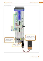
Страница 145: ...13 Motor Driver www freenove com support freenove com Hardware connection Change the jumper cap position to change supply voltage for motor Logic voltage supply end must select 3 3V Switch on the module when using ...

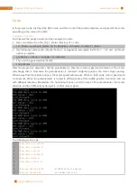
Страница 146: ...sudo Motor After the program is executed shift the potentiometer then the rotation speed and direction of the motor will change with it And when the potentiometer is turned to midpoint position the motor stops running When away from the middle position the motor speed will increase When to both ends motor speed reach to maximum When the potentiometer is turned to different side of the middle posit...

Страница 147: ...determine the direction and speed of the motor according to the ADC value to be input void motor int ADC int value ADC 128 if value 0 digitalWrite motoRPin1 HIGH digitalWrite motoRPin2 LOW printf turn Forward n else if value 0 digitalWrite motoRPin1 LOW digitalWrite motoRPin2 HIGH printf turn Back n else digitalWrite motoRPin1 LOW digitalWrite motoRPin2 LOW printf Motor Stop n softPwmWrite enableP...

Страница 148: ...oRPin2 outputs high level to control motor run with reversed direction When the ADC value is equal to 128 motoRPin1 and motoRPin2 output low level then the motor stops And then determine PWM duty cycle according to the difference between ADC value and 128 Because the absolute difference value stays within 0 128 We need to use the map subfunction mapping the difference value to range of 0 255 Final...

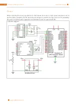
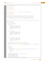
Страница 149: ...or stops running When away from the middle position the motor speed will increase When to both ends motor speed reach to maximum When the potentiometer is turned to different side of the middle position the motor will run with different direction Meanwhile the terminal will print out ADC value of the potentiometer the motor direction and the PWM duty cycle used to control motor speed The following...

Страница 150: ...return toHigh toLow value fromLow fromHigh fromLow toLow motor function determine the direction and speed of the motor according to the ADC value to be input def motor ADC value ADC 128 if value 0 GPIO output motoRPin1 GPIO HIGH GPIO output motoRPin2 GPIO LOW print Turn Forward elif value 0 GPIO output motoRPin1 GPIO LOW GPIO output motoRPin2 GPIO HIGH print Turn Backward else GPIO output motoRPin...

Страница 151: ...reversed direction When the ADC value is equal to 128 make motoRPin1 and motoRPin2 output low level then the motor stops And then determine PWM duty cycle according to the difference between ADC value and 128 Because the absolute difference value stays within 0 128 We need to use the map subfunction mapping the difference value to range of 0 100 Finally print out the duty cycle def motor ADC value...

Страница 152: ...t 14 1 1 Relay Motor In this project we will use a push button to control a relay and drive the motor Component List Raspberry Pi 3B x1 GPIO Expansion Board Wire x1 BreadBoard x1 Jumper 9V battery prepared by yourself battery line Breadboard extension x1 Resistor 10kΩ x2 Resistor 1kΩ x1 Resistor 220Ω x1 NPN transistor x1 Relay x1 Motor x1 Push button x1 LED x1 Diode x1 ...

Страница 153: ...inductance L is the henry H 1H 1000mH 1mH 1000μH Inductor is an energy storage device that converts electrical energy into magnetic energy Generally it consists of winding coil with a certain amountof inductance Inductor will hinder the changing currentpassing through the inductor When the current passing through inductor increases it will attempt to hinder the increasing trend of current and when...

Страница 154: ...com Circuit Pay attention to the power supply voltage needed for the components in circuit in which the relay needs power supply voltage 5V and the motor needs 3 3V Additionally a LED is used as an indicator for the relay turned on or turned off Schematic diagram ...

Страница 155: ...155 Chapter 14 Relay Motor www freenove com support freenove com Hardware connection OFF 3 3V ...

Страница 156: ...ess the button again the relay is closed the Motor stops running and the LED is turned off The following is the program code 1 2 3 4 5 6 7 8 9 10 11 12 13 14 15 16 17 18 19 20 21 22 23 24 25 26 include wiringPi h include stdio h define relayPin 0 define the relayPin define buttonPin 1 define the buttonPin int relayState LOW store the State of relay int buttonState HIGH store the State of button in...

Страница 157: ...ting if millis lastChangeTime captureTime if button state is changed update the data if reading buttonState buttonState reading if the state is low the action is pressing if buttonState LOW printf Button is pressed n relayState relayState if relayState printf turn on relay n else printf turn off relay n if the state is high the action is releasing else printf Button is released n digitalWrite rela...

Страница 158: ...12 13 14 15 16 17 18 19 20 21 22 23 24 25 26 27 28 29 30 31 32 33 34 import RPi GPIO as GPIO import time relayPin 11 define the relayPin buttonPin 12 define the buttonPin debounceTime 50 def setup print Program is starting GPIO setmode GPIO BOARD Numbers GPIOs by physical location GPIO setup relayPin GPIO OUT Set relayPin s mode is output GPIO setup buttonPin GPIO IN def loop relayState False last...

Страница 159: ...print Button is released GPIO output relayPin relayState lastButtonState reading def destroy GPIO output relayPin GPIO LOW relay off GPIO cleanup Release resource if __name__ __main__ Program start from here setup try loop except KeyboardInterrupt destroy The code is in the same logic as TableLamp code above ...

Страница 160: ...ontrol the speed and steering of the motor before In this chapter we will learn a kind of motor that can rotate to a specific angle servo Project 15 1 Servo Sweep First let s learn how to make the servo rotate Component List Raspberry Pi 3B x1 GPIO Expansion Board Wire x1 BreadBoard x1 Jumper Servo x1 ...

Страница 161: ...uding two for electric power line positive 2 VCC red negative 3 GND brown and the signal line 1 Signal orange We use 50Hz PWM signal with a duty cycle in a certain range to drive the servo The lasting time 0 5ms 2 5ms of PWM single cycle high level corresponds to the servo angle 0 degrees 180 degree linearly Part of the corresponding values are as follows High level time Servo angle 0 5ms 0 degree...

Страница 162: ...Chapter 15 Servo 162 www freenove com support freenove com Circuit Pay attention to the power supply for stepping motor is 5v and don t confuse the line sequence Schematic diagram Hardware connection ...

Страница 163: ...16 17 18 19 20 21 22 23 24 25 26 27 28 include wiringPi h include softPwm h include stdio h define OFFSET_MS 3 Define the unit of servo pulse offset 0 1ms define SERVO_MIN_MS 5 OFFSET_MS define the pulse duration for minimum angle of servo define SERVO_MAX_MS 25 OFFSET_MS define the pulse duration for maximum angle of servo define servoPin 1 define the GPIO number connected to servo long map long ...

Страница 164: ...50 Hz pulse namely cycle for 20ms is required to control Servo In function softPwmCreate int pin int initialValue int pwmRange the unit of third parameter pwmRange is 100US namely 0 1ms In order to get the PWM with cycle of 20ms the pwmRange shouldebe set to 200 So in subfunction of servoInit we create a PWM pin with pwmRange 200 void servoInit int pin initialization function for servo PWM pin sof...

Страница 165: ...rees and map the angle to the pulse width and then output it void servoWrite int pin int angle Specif a certain rotation angle 0 180 for the servo if angle 180 angle 180 if angle 0 angle 0 softPwmWrite pin map angle 0 180 SERVO_MIN_MS SERVO_MAX_MS Finally in the while cycle of main function use two for cycle to make servo rotate from 0 degrees to 180 degrees and then from 180 degrees to 0 degrees ...

Страница 166: ...ine pulse duty cycle for minimum angle of servo SERVO_MAX_DUTY 12 5 OFFSE_DUTY define pulse duty cycle for maximum angle of servo servoPin 12 def map value fromLow fromHigh toLow toHigh return toHigh toLow value fromLow fromHigh fromLow toLow def setup global p GPIO setmode GPIO BOARD Numbers GPIOs by physical location GPIO setup servoPin GPIO OUT Set servoPin s mode is output GPIO output servoPin...

Страница 167: ...ds to PWM pulse width 0 5 2 5ms within cycle 20ms and to duty cycle 2 5 12 5 In subfunction servoWrite angle map the angle to duty cycle to output the PWM then the servo will rotate a specific angle However in practice due to the manufacture error of each servo pulse width will also have deviation So we define a minimum pulse width and a maximum one and an error offset OFFSE_DUTY 0 5 define pulse ...

Страница 168: ...make servo rotate from 0 degrees to 180 degrees and then from 180 degrees to 0 degrees def loop while True for dc in range 0 181 1 make servo rotate from 0 to 180 servoWrite dc Write to servo time sleep 0 001 time sleep 0 5 for dc in range 180 1 1 make servo rotate from 180 to 0 servoWrite dc time sleep 0 001 time sleep 0 5 ...

Страница 169: ...le but can not rotate constantly In this chapter we will learn a motor which can rotate not only constantly but also to a specific angle stepping motor Using stepping motor can achieve higher accuracy of mechanical motion easily Project 16 1 Stepping Motor In this project we will learn how to drive stepping motor and understand its working principle Component List Raspberry Pi 3B x1 GPIO Expansion...

Страница 170: ... and pulse number and not affected by the load changes A small four phase deceleration stepping motor is shown as follows The schematic diagram of four phase stepping motor is shown below The outside piece is the stator and the inside is the rotor of the motor There are a certain number of coils usually integer multiple of phases number in the stator and when powered on an electromagnet will be fo...

Страница 171: ...D the rotor will rotate in anti clockwise direction Stepping motor has other control methods such as connect A phase then connect A B phase the stator will be located in the middle of the A B only a half step This way can improve the stability of stepping motor and reduce noise the sequence of coil powered on is A AB B BC C CD D DA A the rotor will rotate in accordance with the order a half step b...

Страница 172: ...the output signal A D and4 LED is integrated in the board to indicate the state of signals The PWR interface can be used as a power supply for stepping motor By default PWR and VCC are connected by a short circuit Circuit When building the circuit the rated voltage of the stepping motor 5V and use the breadboard power supply independently and do not use the RPi power supply Additionally breadboard...

Страница 173: ...173 Chapter 16 Stepping Motor www freenove com support freenove com Hardware connection ...

Страница 174: ...20 21 22 23 24 25 26 27 28 29 include stdio h include wiringPi h const int motorPins 1 4 5 6 define pins connected to four phase ABCD of stepping motor const int CCWStep 0x01 0x02 0x04 0x08 define power supply order for coil for rotating anticlockwise const int CWStep 0x08 0x04 0x02 0x01 define power supply order for coil for rotating clockwise as for four phase stepping motor four steps is a cycl...

Страница 175: ...2 rotating 360 clockwise a total of 2048 steps in a circle namely 512 cycles delay 500 moveSteps 0 3 512 rotating 360 anticlockwise delay 500 return 0 In the code define four pins of stepping motor and coil power supply order of four steps rotation mode const int motorPins 1 4 5 6 define pins connected to four phase ABCD of stepper motor const int CCWStep 0x01 0x02 0x04 0x08 define power supply or...

Страница 176: ...han 3ms otherwise it will exceed speed limit of the motor ms 3 delay ms Subfunction moveSteps int dir int ms int steps is used to specific cycle number of stepping motor void moveSteps int dir int ms int steps int i for i 0 i steps i moveOnePeriod dir ms Subfunction motorStop is used to stop the stepping motor void motorStop function used to stop rotating int i for i 0 i 4 i digitalWrite motorPins...

Страница 177: ... 0x04 0x02 0x01 define power supply order for coil for rotating clockwise def setup print Program is starting GPIO setmode GPIO BOARD Numbers GPIOs by physical location for pin in motorPins GPIO setup pin GPIO OUT as for four phase stepping motor four steps are a cycle the function is used to drive the stepping motor clockwise or anticlockwise to take four steps def moveOnePeriod direction ms for ...

Страница 178: ...lockwise CWStep 0x08 0x04 0x02 0x01 define power supply order for coil for rotating clockwise Subfunction moveOnePeriod direction ms will drive the stepping motor rotating four step clockwise or anticlockwise four step as a cycle Where parameter dir indicates the rotation direction if dir is 1 the servo will rotate forward otherwise it rotates to reverse direction Parameter ms indicates the time b...

Страница 179: ... def motorStop for i in range 0 4 1 GPIO output motorPins i GPIO LOW Finally in the while cycle of main function rotate one circle clockwise and then one circle anticlockwise According to the previous knowledgeof the stepping motor it can be known that the stepping motor rotation for one circle requires 2048 steps that is 2048 4 512 cycle while True moveSteps 1 3 512 rotating 360 clockwise a total...

Страница 180: ...peripherals can be connected to RPi so GPIO resource is very precious Can we make flowing water light with less GPIO In this chapter we will learn a component 74HC595 which can achieve the target Project 17 1 Flowing Water Light Now let s learn how to use 74HC595 to make a flowing water light with less GPIO Component List Raspberry Pi 3B x1 GPIO Extension Board Wire x1 BreadBoard x1 Jumper 74HC595...

Страница 181: ...arallel data output VCC 16 The positive electrode of power supply the voltage is 2 6V GND 8 The negative electrode of power supply DS 14 Serial data Input OE 13 Enable output When this pin is in high level Q0 Q7 is in high resistance state When this pin is in low level Q0 Q7 is in output mode ST_CP 12 Parallel update output when its electrical level is rising it will update the parallel data outpu...

Страница 182: ...Chapter 17 74HC595 LEDBar Graph 182 www freenove com support freenove com Circuit Schematic diagram Hardware connection ...

Страница 183: ...ghtWater02 After the program is executed LEDBar Graph begin to display flowing water light from left to right then from right to left The following is the program code 1 2 3 4 5 6 7 8 9 10 11 12 13 14 15 16 17 18 19 20 21 22 23 24 25 26 27 28 29 include wiringPi h include stdio h include wiringShift h define dataPin 0 DS Pin of 74HC595 Pin14 define latchPin 2 ST_CP Pin of 74HC595 Pin12 define cloc...

Страница 184: ... LSBFIRST x digitalWrite latchPin HIGH x 1 delay 100 return 0 In the code we configure three pins to control the 74HC595 And define a one byte variable to control the state of 8 LEDs through the 8 bits of the variable The LED lights on when the corresponding bit is 1 If the variable is assigned to 0x01 that is 00000001 in binary there will be only one LED on x 0x01 In the while cycle of main funct...

Страница 185: ...cPin low repeat for 8 bits The 8 bit value is returned by the function void shiftOut uint8_t dPin uint8_t cPin uint8_t order uint8_t val void _shiftOut uint8_t dPin uint8_t cPin uint8_t order uint8_t val This is used to shift an 8 bit data value out with the data being sent out on dPin and the clock being sent out on the cPin order is as above Data is clocked out on the rising or falling edge ie d...

Страница 186: ...rder LSBFIRST GPIO output dPin 0x01 val i 0x01 and GPIO HIGH or GPIO LOW elif order MSBFIRST GPIO output dPin 0x80 val i 0x80 and GPIO HIGH or GPIO LOW GPIO output cPin GPIO HIGH def loop while True x 0x01 for i in range 0 8 GPIO output latchPin GPIO LOW Output low level to latchPin shiftOut dataPin clockPin LSBFIRST x Send serial data to 74HC595 GPIO output latchPin GPIO HIGH Output high level to...

Страница 187: ...get First define a variable x 0x01 binary 00000001 When it is transferred to the output port of 74HC595 the low bit outputs high level then a LED is turned on Next x is shifted one bit when x is transferred to the output port of 74HC595 once again the LED turned on will be shifted Repeat the operation the effect of flowing water light will be formed If the direction of the shift operation for x is...

Страница 188: ...his chapter we will learn a new component 7 segment display Project 18 1 7 segment display We will use 74HC595 to control 7 segment display and make it display sixteen decimal character 0 F Component List Raspberry Pi 3B x1 GPIO Extension Board Wire x1 BreadBoard x1 Jumper 74HC595 x1 7 segment display x1 Resistor 220Ω x8 ...

Страница 189: ...m the above circuit diagram that we can control the state of each LED separately So through combining LED with different state we can display different numbers For example display figure 0 we need to turn on LED segment A B C D E F and turn off LED segment G and DP In this project we use a display 7 segment common anode Therefore when the input low level to a LED segment the LED will be turned on ...

Страница 190: ...Chapter 18 74HC595 7 segment display 190 www freenove com support freenove com Circuit Schematic diagram Hardware connection ...

Страница 191: ... 3 Then run the generated file SevenSegmentDisplay sudo SevenSegmentDisplay After the program is executed SevenSegmentDisplay starts to display the character 0 F successively The following is the program code 1 2 3 4 5 6 7 8 9 10 11 12 13 14 15 16 17 18 19 20 21 22 23 24 25 26 27 include wiringPi h include stdio h include wiringShift h define dataPin 0 DS Pin of 74HC595 Pin14 define latchPin 2 ST_...

Страница 192: ...of num i digitalWrite latchPin LOW _shiftOut dataPin clockPin MSBFIRST num i 0x7f Use the 0x7f to display the decimal point digitalWrite latchPin HIGH delay 500 return 0 First put encoding of 0 F into the array unsigned char num 0xc0 0xf9 0xa4 0xb0 0x99 0x92 0x82 0xf8 0x80 0x90 0x88 0x83 0xc6 0xa1 0x86 0x8e In the for cycle of loop function use 74HC595 to output contents of array num successively ...

Страница 193: ... 18 19 20 21 22 23 24 25 26 27 28 29 30 31 32 import RPi GPIO as GPIO import time LSBFIRST 1 MSBFIRST 2 define the pins connect to 74HC595 dataPin 11 DS Pin of 74HC595 Pin14 latchPin 13 ST_CP Pin of 74HC595 Pin12 clockPin 15 CH_CP Pin of 74HC595 Pin11 SevenSegmentDisplay display the character 0 F successively num 0xc0 0xf9 0xa4 0xb0 0x99 0x92 0x82 0xf8 0x80 0x90 0x88 0x83 0xc6 0xa1 0x86 0x8e def s...

Страница 194: ...array num 0xc0 0xf9 0xa4 0xb0 0x99 0x92 0x82 0xf8 0x80 0x90 0x88 0x83 0xc6 0xa1 0x86 0x8e In the for cycle of loop function use 74HC595 to output contents of array num successively SevenSegmentDisplay can correctly display the corresponding characters Pay attention to that in shiftOut function the transmission bit flag bit highest bit will be transmitted preferentially for i in range 0 len num GPI...

Страница 195: ...ve com Project 18 2 4 Digit 7 segment display Now let s try to control more Digit 7 segment display Component List Raspberry Pi 3B x1 GPIO Expansion Board Wire x1 BreadBoard x1 Jumper 74HC595 x1 PNP transistor x4 4 Digit 7 segment display x1 Resistor 220Ω x8 Resistor 1KΩ x4 ...

Страница 196: ... them is that 4 Digit display in turn one by one not together First send high level to common end of the first tube and send low level to the rest of the three common end and then send content to 8 LED cathode pins of the first tube At this time the first 7 segment display will display content and the rest three one in closed state Similarly the second third fourth 7 segment display the content in...

Страница 197: ...197 Chapter 18 74HC595 7 segment display www freenove com support freenove com Circuit Schematic diagram ...

Страница 198: ...Chapter 18 74HC595 7 segment display 198 www freenove com support freenove com Hardware connection ...

Страница 199: ...16 17 18 19 20 21 22 23 24 25 26 27 include wiringPi h include stdio h include wiringShift h include signal h include unistd h define dataPin 5 DS Pin of 74HC595 Pin14 define latchPin 4 ST_CP Pin of 74HC595 Pin12 define clockPin 1 CH_CP Pin of 74HC595 Pin11 const int digitPin 0 2 3 12 Define 7 segment display common pin character 0 9 code of common anode 7 segment display unsigned char num 0xc0 0x...

Страница 200: ...ction for 7 segment display int delays 1 outData 0xff selectDigit 0x01 select the first and display the single digit outData num dec 10 delay delays display duration outData 0xff selectDigit 0x02 select the second and display the tens digit outData num dec 100 10 delay delays outData 0xff selectDigit 0x04 select the third and display the hundreds digit outData num dec 1000 100 delay delays outData...

Страница 201: ...common end character encoding and a variable counter to be displayed counter define dataPin 5 DS Pin of 74HC595 Pin14 define latchPin 4 ST_CP Pin of 74HC595 Pin12 define clockPin 1 CH_CP Pin of 74HC595 Pin11 const int digitPin 0 2 3 12 Define the pin of 7 segment display common end character 0 9 code of common anode 7 segment display unsigned char num 0xc0 0xf9 0xa4 0xb0 0x99 0x92 0x82 0xf8 0x80 0...

Страница 202: ...o you will see different digit is in a mess If the time is set long enough you will see that every digit is display independent void display int dec display function for 7 segment display selectDigit 0x01 select the first and display the single digit outData num dec 10 delay 1 display duration selectDigit 0x02 Select the second and display the tens digit outData num dec 100 10 delay 1 selectDigit ...

Страница 203: ...Mode clockPin OUTPUT set the pin connected to 7 segment display common end to output mode for i 0 i 4 i pinMode digitPin i OUTPUT digitalWrite digitPin i LOW signal SIGALRM timer configure the timer alarm 1 set the time of timer to 1s In the while cycle make the digital display variable counter value The value will change in function timer so the content displayed by 7 segment display will change ...

Страница 204: ...1 MSBFIRST 2 define the pins connect to 74HC595 dataPin 18 DS Pin of 74HC595 Pin14 latchPin 16 ST_CP Pin of 74HC595 Pin12 clockPin 12 SH_CP Pin of 74HC595 Pin11 num 0xc0 0xf9 0xa4 0xb0 0x99 0x92 0x82 0xf8 0x80 0x90 digitPin 11 13 15 19 Define the pin of 7 segment display common end counter 0 Variable counter the number will be dislayed by 7 segment display t 0 define the Timer object def setup GPI...

Страница 205: ...on for 7 segment display outData 0xff eliminate residual display selectDigit 0x01 Select the first and display the single digit outData num dec 10 time sleep 0 003 display duration outData 0xff selectDigit 0x02 Select the second and display the tens digit outData num dec 100 10 time sleep 0 003 outData 0xff selectDigit 0x04 Select the third and display the hundreds digit outData num dec 1000 100 t...

Страница 206: ...LOW if digit 0x08 0x08 else GPIO HIGH GPIO output digitPin 1 GPIO LOW if digit 0x04 0x04 else GPIO HIGH GPIO output digitPin 2 GPIO LOW if digit 0x02 0x02 else GPIO HIGH GPIO output digitPin 3 GPIO LOW if digit 0x01 0x01 else GPIO HIGH Subfunction outData data is used to make the 74HC595 output a 8 bit data immediately def outData data function used to output data for 74HC595 GPIO output latchPin ...

Страница 207: ...ll be executed again def timer timer function global counter global t t threading Timer 1 0 timer reset time of timer to 1s t start Start timing counter 1 print counter d counter Subfunction setup configure all input output modes for the GPIO pin used Finally in loop function make the digital tube display variable counter value in the while cycle The value will change in function timer so the cont...

Страница 208: ...even SegmentDisplay And we will continue to use the 74HC595 to control more LED LEDMatrix Project 19 1 LED Matrix In this project we will use two 74HC595 to control a monochrome LEDMatrix 8 8 to make it display some graphics and characters Component List Raspberry Pi 3B x1 GPIO Extension Board Wire x1 BreadBoard x1 Jumper 74HC595 x2 8 8 LEDMatrix x1 Resistor 220Ω x8 ...

Страница 209: ... operation and save the ports positive pole of LEDs in each row and negative pole of LEDs in each column are respectively connected together inside LED matrix module which is called Common Anode There is another form Negative pole of LEDs in each row and positive pole of LEDs in each column are respectively connected together which is called Common Cathode The one we use in this project is a commo...

Страница 210: ...ond column turn off the seventh column and display the 8th column and then start from the first column again like the control of Graph LEDBar The whole progress will be repeated rapidly and circularly Due to afterglow effect of LED and visual residual effect of human eyes we will see a picture of a smiling face directly rather than LED are turned on one column by one column although in fact it is ...

Страница 211: ...19 74HC595 LED Matrix www freenove com support freenove com Circuit In this project circuit the power pin of 74HC595 is connected to 3 3V It can also be connected to 5V to make LEDMatrix brighter Schematic diagram ...

Страница 212: ...Chapter 19 74HC595 LED Matrix 212 www freenove com support freenove com Hardware connection Second stage 74HC595 B First stage 74HC595 A ...

Страница 213: ..._Ultimate_Starter_Kit_for_Raspberry_Pi Code C_Code 19 1 1_LEDMatrix 2 Use following command to compile LEDMatrix c and generate executable file LEDMatrix gcc LEDMatrix c o LEDMatrix lwiringPi 3 Then run the generated file LEDMatrix sudo LEDMatrix After the program is executed LEDMatrix will display a smiling face and then the display scrolling character 0 F circularly The following is the program ...

Страница 214: ...ST digitalWrite dPin 0x01 val i 0x01 HIGH LOW delayMicroseconds 10 else if order MSBFIRST digitalWrite dPin 0x80 val i 0x80 HIGH LOW delayMicroseconds 10 digitalWrite cPin HIGH delayMicroseconds 10 int main void int i j k unsigned char x if wiringPiSetup 1 when initialize wiring failed print messageto screen printf setup wiringPi failed return 1 pinMode dataPin OUTPUT pinMode latchPin OUTPUT pinMo...

Страница 215: ...ormation to start from the first column for i k i 8 k i digitalWrite latchPin LOW _shiftOut dataPin clockPin MSBFIRST data i _shiftOut dataPin clockPin MSBFIRST x digitalWrite latchPin HIGH x 1 delay 1 return 0 The first for cycle in the while cycle is used to display a static smile Display column information from left to right one column by one column totally 8 columns Repeat 500 times to ensure ...

Страница 216: ...f times and the more times the number of repetitions the longer the single frame display the slower the rolling for k 0 k sizeof data 8 k sizeof data total number of 0 F columns for j 0 j 20 j times of repeated displaying LEDMatrix in every frame the bigger the j the longer the display time x 0x80 Set the column information to start from the first column for i k i 8 k i digitalWrite latchPin LOW s...

Страница 217: ...n 15 SH_CP Pin of 74HC595 Pin11 pic 0x1c 0x22 0x51 0x45 0x45 0x51 0x22 0x1c data of smiling face data data of 0 F 0x00 0x00 0x00 0x00 0x00 0x00 0x00 0x00 0x00 0x00 0x3E 0x41 0x41 0x3E 0x00 0x00 0 0x00 0x00 0x21 0x7F 0x01 0x00 0x00 0x00 1 0x00 0x00 0x23 0x45 0x49 0x31 0x00 0x00 2 0x00 0x00 0x22 0x49 0x49 0x36 0x00 0x00 3 0x00 0x00 0x0E 0x32 0x7F 0x02 0x00 0x00 4 0x00 0x00 0x79 0x49 0x49 0x46 0x00 0...

Страница 218: ...t shift data of line information to first stage 74HC959 shiftOut dataPin clockPin MSBFIRST x then shift data of column information to second stage 74HC959 GPIO output latchPin GPIO HIGH Output data of two stage 74HC595 at the same time time sleep 0 001 display the next column x 1 for k in range 0 len data 8 len data total number of 0 F columns for j in range 0 20 times of repeated displaying LEDMa...

Страница 219: ...O HIGH Output data of two stage 74HC595 at the same time time sleep 0 001 display the next column x 1 The second for cycle is used to display scrolling characters 0 F totally 18 8 144 columns Display the 0 8 column 1 9 column 2 10 column 138 144 column in turn to achieve scrolling effect The display of each frame is repeated a certain number of times and the more times the number of repetitions th...

Страница 220: ...interface which connects the serial input parallel output module to LCD1602 We just use 4 lines to the operate LCD1602 easily The serial to parallel chip used in this moduleis PCF8574 PCF8574A andits default I2C address is 0x27 0x3F and you can view all the RPI bus on your I2C device address through command i2cdetect y 1 to refer to the configuration I2C section below below is the PCF8574 pin sche...

Страница 221: ...e just 4 pins to control LCD1602 with 16 pins easily through I2C interface In this project we will use I2CLCD1602 to display some static characters and dynamic variables Component List Raspberry Pi 3B x1 GPIO Extension Board Wire x1 BreadBoard x1 Jumper I2C LCD1602 Module x1 ...

Страница 222: ...Chapter 20 LCD1602 222 www freenove com support freenove com Circuit Note that the power supply for I2CLCD1602 in this circuit is 5V Schematic diagram Hardware connection ...

Страница 223: ...ing command to compile I2CLCD1602 c and generate executable file I2CLCD1602 gcc I2CLCD1602 c o I2CLCD1602 lwiringPi lwiringPiDev 4 Then run the generated file I2CLCD1602 sudo I2CLCD1602 After the program is executed LCD1602 screen will display current CPU temperature and system time If there is no display or the display is not clear rotate white knob in back of LCD to adjust the contrast of LCD160...

Страница 224: ...elsius degrees printf CPU s temperature 2f n CPU_temp lcdPosition lcdhd 0 0 set the LCD cursor position to 0 0 lcdPrintf lcdhd CPU 2fC CPU_temp Display CPU temperature on LCD fclose fp void printDataTime used to print system time time_t rawtime struct tm timeinfo time rawtime get system time timeinfo localtime rawtime convert to local time printf s n asctime timeinfo lcdPosition lcdhd 0 1 set the ...

Страница 225: ...define pcf8574_address 0x3F default I2C address of Pcf8574A define BASE 64 BASE is not less than 64 Define the output pins of the PCF8574 which are directly connected to the LCD1602 pin define RS BASE 0 define RW BASE 1 define EN BASE 2 define LED BASE 3 define D4 BASE 4 define D5 BASE 5 define D6 BASE 6 define D7 BASE 7 Then in main function initialize the PCF8574 set all the pins to output mode ...

Страница 226: ...tored in the sys class thermal thermal_zone0 temp file We need read contents of the file and converts it to temperature value stored in variable CPU_temp and use lcdPrintf to display it on LCD void printCPUTemperature subfunction used to print CPU temperature FILE fp char str_temp 15 float CPU_temp CPU temperature data is stored in this directory fp fopen sys class thermal thermal_zone0 temp r fge...

Страница 227: ... to execute python code I2CLCD1602 py python I2CLCD1602 py After the program is executed LCD1602 screen will display current CPU temperature and system time If there is no display or the display is not clear rotate white knob in back of LCD to adjust the contrast of LCD1602 until the screen can display clearly The following is the program code 1 2 3 4 5 6 7 8 9 10 11 12 13 14 15 16 from PCF8574 im...

Страница 228: ... Create LCD passing in MCP GPIO adapter lcd Adafruit_CharLCD pin_rs 0 pin_e 2 pins_db 4 5 6 7 GPIO mcp if __name__ __main__ print Program is starting try loop except KeyboardInterrupt destroy Two modules are used in the code PCF8574 py and Adafruit_LCD1602 py These two documents and the code file are stored in the samedirectory andneither of them is dispensable Please do not delete PCF8574 py is u...

Страница 229: ...ef get_cpu_temp get CPU temperature and store it into file sys class thermal thermal_zone0 temp tmp open sys class thermal thermal_zone0 temp cpu tmp read tmp close return 2f format float cpu 1000 C Subfunction used to get time def get_time_now get the time return datetime now strftime H M S Details about PCF8574 py and Adafruit_LCD1602 py Module PCF8574 This module provides two classes PCF8574_I2...

Страница 230: ...PIO Expansion Board Wire x1 BreadBoard x1 DHT11 x1 Resistor 10kΩ x1 Jumper Component knowledge Temperature Humidity Sensor DHT11 is a compound temperature humidity sensor andthe output digital signal has been calibrated inside It has 1S s initialization time after powered up The operating voltage is within the range of 3 3V 5 5V SDA pin is a data pin which is used to communicate with other device ...

Страница 231: ...231 Chapter 21 Hygrothermograph DHT11 www freenove com support freenove com Circuit Schematic diagram Hardware connection ...

Страница 232: ...custom header file will be compiled at the same time gcc DHT cpp DHT11 cpp o DHT11 lwiringPi 3 Run the generated file DHT11 sudo DHT11 After the program is executed the terminal window will display the current total number of reading times the read state as well as the temperature and humidity value As is shown below The following is the program code 1 2 3 4 5 6 7 8 9 10 11 12 13 14 15 include wir...

Страница 233: ...return 1 In this project code we use a custom library file DHT hpp It is located in the same directory with program files DHT11 cpp and DHT cpp and methods for reading DHT sensor are provided in the library file By using this library we can easily read the DHT sensor First create a DHT class object in the code DHT dht And then in the while cycle use chk dht readDHT11 DHT11_Pin to read the DHT11 an...

Страница 234: ...int h read return flag of sensor define DHTLIB_OK 0 define DHTLIB_ERROR_CHECKSUM 1 define DHTLIB_ERROR_TIMEOUT 2 define DHTLIB_INVALID_VALUE 999 define DHTLIB_DHT11_WAKEUP 18 define DHTLIB_DHT_WAKEUP 1 define DHTLIB_TIMEOUT 100 class DHT public double humidity temperature use to store temperature and humidity data read int readDHT11 int pin read DHT11 private int bits 5 Buffer to receiver data int...

Страница 235: ...HT11 read DHT11 and get a return value Then determine whether data read is normal according to the return value print The sumCnt is d t chk d sumCnt chk if chk is dht DHTLIB_OK read DHT11 and get a return value Then determine whether data read is normal according to the return value print DHT11 OK elif chk is dht DHTLIB_ERROR_CHECKSUM data check has errors print DHTLIB_ERROR_CHECKSUM elif chk is d...

Страница 236: ...Cnt chk if chk is dht DHTLIB_OK read DHT11 and get a return value Then determine whether data read is normal according to the return value print DHT11 OK elif chk is dht DHTLIB_ERROR_CHECKSUM data check has errors print DHTLIB_ERROR_CHECKSUM elif chk is dht DHTLIB_ERROR_TIMEOUT reading DHT times out print DHTLIB_ERROR_TIMEOUT else other errors print Other error Finally print the results print Humi...

Страница 237: ... of a single button before In this chapter we will learn a device which integrates a number of key matrix keyboard Project 22 1 Matrix Keypad In this project we will try to get every key code on the Keypad work Component List Raspberry Pi 3B x1 GPIO Expansion Board Wire x1 BreadBoard x1 4x4 Matrix Keypad x1 Jumper ...

Страница 238: ...olumn Such connection can reduce the occupation of processor port Internal circuit is shown below The usage method is similar to the Matrix LED namely uses a row scan or column scanning method to detect the state of key on each column or row Take column scanning method as an example send low level to the first 1 column Pin1 detect level state of row 5 6 7 8 to judge whether the key A B C D are pre...

Страница 239: ...239 Chapter 22 Matrix Keypad www freenove com support freenove com Circuit Schematic diagram ...

Страница 240: ...Chapter 22 Matrix Keypad 240 www freenove com support freenove com Hardware connection ...

Страница 241: ...pad cpp Keypad cpp and Key cpp generate executable file MatrixKeypad And the custom header file will be compiled at the same time gcc MatrixKeypad cpp Keypad cpp Key cpp o MatrixKeypad lwiringPi 3 Run the generated file MatrixKeypad sudo MatrixKeypad After the program is executed press any key on the MatrixKeypad the terminal will print out the corresponding key code As is shown below The followin...

Страница 242: ...s library file provides a method to read the keyboard By using this library we can easily read the matrix keyboard First define the information of the matrix keyboard used in this project the number of rows and columns code of each key and GPIO pin connected to each column and each row It is necessary to include the header file Keypad hpp include Keypad hpp include stdio h const byte ROWS 4 four r...

Страница 243: ... the Keypad library are described below class Keypad Keypad char userKeymap byte row byte col byte numRows byte numCols Constructor the parameters are key code of keyboard row pin column pin the number of rows the number of columns char getKey Get the key code of the pressed key If no key is pressed the return value is NULL void setDebounceTime uint Set the debounce time And the default time is 10...

Страница 244: ...llowing is the program code 1 2 3 4 5 6 7 8 9 10 11 12 13 14 15 16 17 18 19 20 21 22 import RPi GPIO as GPIO import Keypad import module Keypad ROWS 4 number of rows of the Keypad COLS 4 number of columns of the Keypad keys 1 2 3 A key code 4 5 6 B 7 8 9 C 0 D rowsPins 12 16 18 22 connect to the row pinouts of the keypad colsPins 19 15 13 11 connect to the column pinouts of the keypad def loop key...

Страница 245: ...ule Keypad ROWS 4 number of rows of the Keypad COLS 4 number of columns of the Keypad keys 1 2 3 A key code 4 5 6 B 7 8 9 C 0 D rowsPins 12 16 18 22 connect to the row pinouts of the keypad colsPins 19 15 13 11 connect to the column pinouts of the keypad And then based on the above information instantiate a Keypad class object to operate the matrix keyboard keypad Keypad Keypad keys rowsPins colsP...

Страница 246: ...ed function the parameters are key code of keyboard row pin column pin the number of rows the number of columns def getKey self Get a pressed key If no key is pressed the return value is keypad NULL def setDebounceTime self ms Set the debounce time And the default time is 10ms def setHoldTime self ms Set the time when the key holds stable state after pressed def isPressed keyChar Judge wether the ...

Страница 247: ...n this project we will make a sense LED with the human body infrared pyroelectric sensors When someone get close to the LED it will light automatically On the contrary it will be out This infrared motion sensor is a kind of sensor which can detect the infrared emitted by human and animals Component List Raspberry Pi 3B x1 GPIO Expansion Board Wire x1 BreadBoard x1 Jumper HC SR501 x1 LED x1 Resisto...

Страница 248: ...g high level time the sensor doesn t sense body anymore H repeatable trigger mode The distinction from L is that it can sense body until body leaves during the period of outputting high level And then it starts to time and output low level after delaying T time 4 Induction block time the induction will stay in block condition and do not induce external signal at a little time less than delay time ...

Страница 249: ...249 Chapter 23 Infrared Motion Sensor www freenove com support freenove com Circuit Schematic diagram Hardware connection ...

Страница 250: ...Kit_for_Raspberry_Pi Code C_Code 23 1 1_SenseLED 2 Use following command to compile SenseLED c and generate executable file SenseLED gcc SenseLED c o SenseLED lwiringPi 3 Run the generated file SenseLED sudo SenseLED After the program is executed try to leave away from or get closed to the Motion Sensor Infrared and observe whether the LED will be turned on or off The terminal window will print ou...

Страница 251: ...pberry_Pi Code Python_Code 23 1 1_SenseLED 2 Use python command to execute code SenseLED py python SenseLED py After the program is executed try to leave away from or get closed to the Motion Sensor Infrared and observe whether the LED will be turned on or off The terminal window will print out the state of LED constantly As is shown below The following is the program code 1 2 3 4 5 6 7 8 9 10 11 ...

Страница 252: ...IO output ledPin GPIO LOW print led off def destroy GPIO cleanup Release resource if __name__ __main__ Program start from here setup try loop except KeyboardInterrupt When Ctrl C is pressed the subprogram destroy will be executed destroy It can be seen that the code is based on the same logic with the ButtonLED code in addition to determining the level of the input signal ...

Страница 253: ... chapter we learn a module which use ultrasonic to measure distance HC SR04 Project 24 1 Ultrasonic Ranging In this project we use ultrasonic ranging module to measure distance and print out the data in the terminal Component List Raspberry Pi 3B x1 GPIO Expansion Board Wire x1 BreadBoard x1 HC SR04 x1 Jumper ...

Страница 254: ...es a transmitter and a receiver The transmitter is used to convert electrical signals electrical energy into sound waves mechanical energy and the function of the receiver is opposite The object picture and the diagram of HC SR04 ultrasonic module are shown below Pin description VCC power supply pin Trig trigger pin Echo Echo pin GND GND Technical specs Working voltage 5V Working current 12mA Mini...

Страница 255: ...255 Chapter 24 Ultrasonic Ranging www freenove com support freenove com Circuit Note that the voltage of ultrasonic module is 5V in the circuit Schematic diagram Hardware connection ...

Страница 256: ...n the ultrasonic module and the object will be displayed in the terminal As is shown below The following is the program code 1 2 3 4 5 6 7 8 9 10 11 12 13 14 15 16 17 18 19 20 21 22 include wiringPi h include stdio h include sys time h define trigPin 4 define echoPin 5 define MAX_DISTANCE 220 define the maximum measured distance define timeOut MAX_DISTANCE 60 calculate timeout according to the max...

Страница 257: ...m distance that is time Out timOut 2 MAX_DISTANCE 100 340 1000000 Theconstant part behind is approximately equal to 58 8 define timeOut MAX_DISTANCE 60 Subfunction getSonar function is used to start the ultrasonic module for a measurement and return the measured distance with unit cm In this function first let trigPin send 10us high level to start the ultrasonic module Then use pulseIn to read ult...

Страница 258: ...Python_Code 24 1 1_UltrasonicRanging 2 Use python command to execute code UltrasonicRanging py python UltrasonicRanging py After the program is executed make the detector of ultrasonic ranging module aim at the plane of an object then the distance between the ultrasonic module and the object will be displayed in the terminal As is shown below The following is the program code 1 2 3 4 5 6 7 8 9 10 ...

Страница 259: ...ting GPIO setmode GPIO BOARD numbers GPIOs by physical location GPIO setup trigPin GPIO OUT set trigPin to output mode GPIO setup echoPin GPIO IN set echoPin to input mode def loop while True distance getSonar print The distance is 2f cm distance time sleep 1 if __name__ __main__ program start from here setup try loop except KeyboardInterrupt when Ctrl C is pressed the program will exit GPIO clean...

Страница 260: ...ultrasonic module with unit cm GPIO output trigPin GPIO HIGH make trigPin send 10us high level time sleep 0 00001 10us GPIO output trigPin GPIO LOW pingTime pulseIn echoPin GPIO HIGH timeOut read plus time of echoPin distance pingTime 340 0 2 0 10000 0 the sound speed is 340m s and calculate distance return distance Finally in the while loop of main function get the measurement distance and print ...

Страница 261: ...PU6050 In this chapter we will learn an attitude sensor which integrates accelerometer and gyroscope MPU6050 Project 25 1 Read MPU6050 We will read acceleration data and gyroscope data of MPU6050 in this project Component List Raspberry Pi 3B x1 GPIO Expansion Board Wire x1 BreadBoard x1 MPU6050 x1 Jumper ...

Страница 262: ...unication protocol and the default address is 0x68 The port description of the MPU6050 module is as follows Pin name Pin number Description VCC 1 Positive pole of power supply with voltage 5V GND 2 Negative pole of power supply SCL 3 I2C communication clock pin SDA 4 I2C communication data pin XDA 5 I2C host data pin which can be connected to other devices XCL 6 I2C host clock pin which can be con...

Страница 263: ...263 Chapter 25 Attitude Sensor MPU6050 www freenove com support freenove com Circuit Note that the power supply voltage for MPU6050 module is 5V in the circuit Schematic diagram Hardware connection ...

Страница 264: ... cpp o MPU6050RAW 3 Then run the generated file MPU6050RAW sudo MPU6050RAW After the program is executed the terminal will display the original acceleration and gyroscope data of MPU6050 as well as the conversion to gravity acceleration and angular velocity as the unit of data As shown in the following figure The following is the program code 1 2 3 4 5 6 7 8 9 10 11 12 13 14 15 16 17 18 include st...

Страница 265: ...ll be compiled as others Class MPU6050 is used to operate the MPU6050 When used first instantiate an object MPU6050 accelgyro In the setup function the MPU6050 is initialized and the result of the initialization will be judged void setup initialize device printf Initializing I2C devices n accelgyro initialize initialize MPU6050 verify connection printf Testing device connections n printf accelgyro...

Страница 266: ...tly read and set MPU6050 Here are some member functions MPU6050 MPU6050 uint8_t address Constructor The parameter is I2C address and the default I2C address is 0x68 void initialize Initialization function used to wake up MPU6050 Range of accelerometer is 2g and range of gyroscope is 250 degrees sec void getMotion6 int16_t ax int16_t ay int16_t az int16_t gx int16_t gy int16_t gz Get the original d...

Страница 267: ...s the unit of data As shown in the following figure The following is the program code 1 2 3 4 5 6 7 8 9 10 11 12 13 14 15 16 17 18 19 20 21 22 23 24 25 import MPU6050 import time mpu MPU6050 MPU6050 instantiate a MPU6050 class object accel 0 3 store accelerometer data gyro 0 3 store gyroscope data def setup mpu dmp_initialize initialize MPU6050 def loop while True accel mpu get_acceleration get ac...

Страница 268: ...data print a g d t d t d t d t d t d accel 0 accel 1 accel 2 gyro 0 gyro 1 gyro 2 print a g 2f g t 2f g t 2f g t 2f d s t 2f d s t 2f d s accel 0 16384 0 accel 1 16384 0 accel 2 16384 0 gyro 0 131 0 gyro 1 131 0 gyro 2 131 0 time sleep 0 1 About class MPU6050 Class MPU6050 This is a class library used to operate MPU6050 which can directly read and set MPU6050 Here are some member functions def __i...

Страница 269: ...mobile phones computers and other equipments to control debug and use RPi GPIO conveniently It also supports many commonly used communication protocol such as serial I2C SPI etc and a lot of equipments like AD DA converter pcf8591 used before and so on Then on this basis through adding some peripheral circuits you can create your own smart home For more details about WebIOPi please refer to http w...

Страница 270: ...Chapter 26 WebIOPi IOT 270 www freenove com support freenove com Circuit Schematic diagram Hardware connection ...

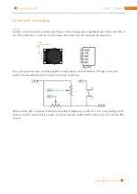
Страница 271: ...tent com doublebind raspi master webiopi pi2bplus patch patch p1 i webiopi pi2bplus patch 4 Run setup sh to start the installation and the process need a period of time to wait sudo setup sh Run After the installation is completed you can use the webiopi command to start running sudo webiopi h c config l log s script d port Options h help Display this help c config file Load config from file l log...

Страница 272: ...Chapter 26 WebIOPi IOT 272 www freenove com support freenove com Click on GPIO Header to enter the GPIO control interface ...

Страница 273: ...s that the model of new generation of RPi CPU is different form old one which result in some of the issues during using WebIOPi has not provide corresponding installation package for latest RPi timely Therefore there are two changes in the configuration and some BUG may exist to cause some problems to WebIOPi function We look forward to that the author of WebIOPi to provide a complete set of the l...

Страница 274: ... finish this chapter you need to prepare the necessary soldering equipments including electric iron and solder We have prepared the general board for you please pay attention to safety when you operate these projects Project 27 1 Solder a Buzzer We have tried to use the buzzer from previous chapter and now we will solder a circuit that when the button is pressed the buzzer sounds This circuit does...

Страница 275: ...275 Chapter 27 Solder Circuit Board www freenove com support freenove com Circuit We will solder the following circuit on the general board Schematic diagram Hardware connection ...
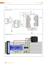
Страница 276: ...er 27 Solder Circuit Board 276 www freenove com support freenove com Solder the Circuit Insert the components in the general board and solder the circuit on the back Effect diagram after soldering Front Back ...

Страница 277: ...t freenove com Test circuit Connect the circuit board to power supply 3 5V You can use Raspberry Pi board or battery box as the power supply Press the push button after connecting the power and then the buzzer will make a sound Anode Cathode Tear the label off ...

Страница 278: ... chapter we have learned to make a flowing water light with LED Now we will solder a circuit board and use the improved code to make a more interesting flowing water light Component list Pin header x5 Resistor 220Ω x8 LED x8 74HC595 x1 Circuit Solder the following circuit on the general board Schematic diagram Hardware connection ...

Страница 279: ...hapter 27 Solder Circuit Board www freenove com support freenove com Solder the Circuit Insert the components in the general board and solder the circuit on the back Effect diagram after soldering Front Back ...

Страница 280: ... from previous ones When this light flows it will bring a long tail C Code 27 2 1 LightWater03 First observe the project result and then analyze the code 1 Use cd command to enter 27 2 1_LightWater03 directory of C code cd Freenove_Ultimate_Starter_Kit_for_Raspberry_Pi Code C_Code 27 2 1_LightWater03 2 Use following command to compile LightWater03 c and generate executable file LightWater03 gcc Li...

Страница 281: ...in LSBFIRST data digitalWrite latchPin HIGH int main void int i j index index current position in array pluseWidth int moveSpeed 100 move speed delay the greater the slower long lastMove Record the last time point of the move if wiringPiSetup 1 when initialize wiring failed print message to screen printf setup wiringPi failed return 1 pinMode dataPin OUTPUT pinMode latchPin OUTPUT pinMode clockPin...

Страница 282: ...e moveSpeed saves the time interval of each move and the greater the value the slower the flowing rate On the contrary the faster the flowing if millis lastMove moveSpeed speed control lastMove millis Record the time point of the move index move to next if index 15 index 0 index to 0 Finally in a for cycle with i 64 modulate output pulse width of PWM square wave And the progress from the beginning...

Страница 283: ...ect to 74HC595 dataPin 11 DS Pin of 74HC595 Pin14 latchPin 13 ST_CP Pin of 74HC595 Pin12 clockPin 15 SH_CP Pin of 74HC595 Pin11 Define an array to save the pulse width of LED Output the signal to the 8 adjacent LEDs in order pluseWidth 0 0 0 0 0 0 0 0 64 32 16 8 4 2 1 0 0 0 0 0 0 0 0 def setup GPIO setmode GPIO BOARD Number GPIOs by its physical location GPIO setup dataPin GPIO OUT GPIO setup latc...

Страница 284: ...e print Program is starting setup try loop except KeyboardInterrupt destroy We can see that this procedure is different from the previous running water lamp we define an array for the modulation of different PWM LED pulse width so that different LED have different brightness Starting from the array index 0 each take an array of 8 adjacent numbers as the LED duty cycle output which in turn increase...

Страница 285: ...e is another for cycle with j 8 And in this cycle compare the cycle number i to the value of the array to determine output high or low level At last the data will be sent to 74HC595 for i in range 0 64 The cycle of PWM is 64 cycles data 0 This loop of output data for j in range 0 8 Calculate the output state of this loop if i pluseWidth j index Calculate the LED state according to the pulse width ...

Страница 286: ...ontact us and we will check and correct it as soon as possible If you are interesting in processing you can learn the Processing pdf in the unzipped folder If you want to learn more about Arduino Raspberry Pi smart cars robots and other interesting products in science and technology please continue to focus on our website We will continue to launch cost effective innovative and exciting products h...

Отзывы: