143
Chapter 13 Motor & Driver
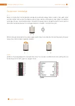
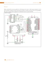
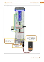
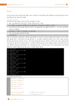
Port description of L293D module is as follows:
Pin name
Pin number
Description
In x
2, 7, 10, 15
Channel x digital signal input pin
Out x
3, 6, 11, 14
Channel x output pin, input high or low level according to In x pin, get
connected to +Vmotor or 0V
Enable1
1
Channel 1 and channel 2 enable pin, high level enable
Enable2
9
Channel 3 and channel 4 enable pin, high level enable
0V
4, 5, 12, 13
Power cathode (GND)
+V
16
Positive electrode (VCC) of power supply, supply voltage 4.5~36V
+Vmotor
8
Positive electrode of load power supply, provide power supply for the Out
pin x, the supply voltage is +V~36V
For more details, please see datasheet.
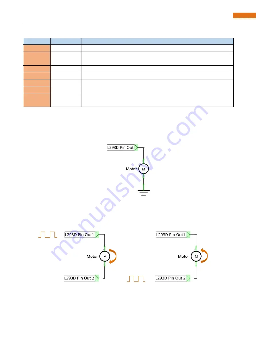
When using L293D to drive DC motor, there are usually two kinds of connection.
Following connection uses one channel, and it can control motor speed through PWM, but the motor can
only rotate in one direction.
Following connection uses two channels: one channel outputs PWM wave, and another channel connects
GND, so you can control the speed of motor. When these two channel signals are exchanged, the current
direction of the motor can be reversed, and the motor will rotate in reverse direction. This can not only
control the speed of motor, but also can control the steering of motor.
In actual use, motor is usually connected to the channel 1 and 2, output different level to in1 and in2 to
control the rotation direction of the motor, and output PWM wave to Enable1 port to control the motor
rotation speed. Or, get motor connected to the channel 3 and 4, output different level to in3 and in4 to
control the motor's rotation direction, and output PWM wave to Enable2 pin to control the motor rotation
speed.
GND
GND
Содержание Ultimate Starter Kit
Страница 1: ...Free your innovation Freenove is an open source electronics platform www freenove com ...
Страница 116: ...Chapter 9 Potentiometer RGBLED 116 www freenove com support freenove com Circuit Schematic diagram ...
Страница 117: ...117 Chapter 9 Potentiometer RGBLED www freenove com support freenove com Hardware connection ...
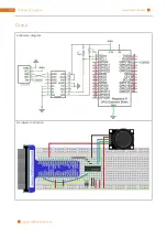
Страница 136: ...Chapter 12 Joystick 136 www freenove com support freenove com Circuit Schematic diagram Hardware connection ...
Страница 155: ...155 Chapter 14 Relay Motor www freenove com support freenove com Hardware connection OFF 3 3V ...
Страница 173: ...173 Chapter 16 Stepping Motor www freenove com support freenove com Hardware connection ...
Страница 182: ...Chapter 17 74HC595 LEDBar Graph 182 www freenove com support freenove com Circuit Schematic diagram Hardware connection ...
Страница 197: ...197 Chapter 18 74HC595 7 segment display www freenove com support freenove com Circuit Schematic diagram ...
Страница 198: ...Chapter 18 74HC595 7 segment display 198 www freenove com support freenove com Hardware connection ...
Страница 239: ...239 Chapter 22 Matrix Keypad www freenove com support freenove com Circuit Schematic diagram ...
Страница 240: ...Chapter 22 Matrix Keypad 240 www freenove com support freenove com Hardware connection ...
Страница 270: ...Chapter 26 WebIOPi IOT 270 www freenove com support freenove com Circuit Schematic diagram Hardware connection ...

