background image

23    Macro

23-32

MOVE_FILE F0 F1 F2

Function: File movement

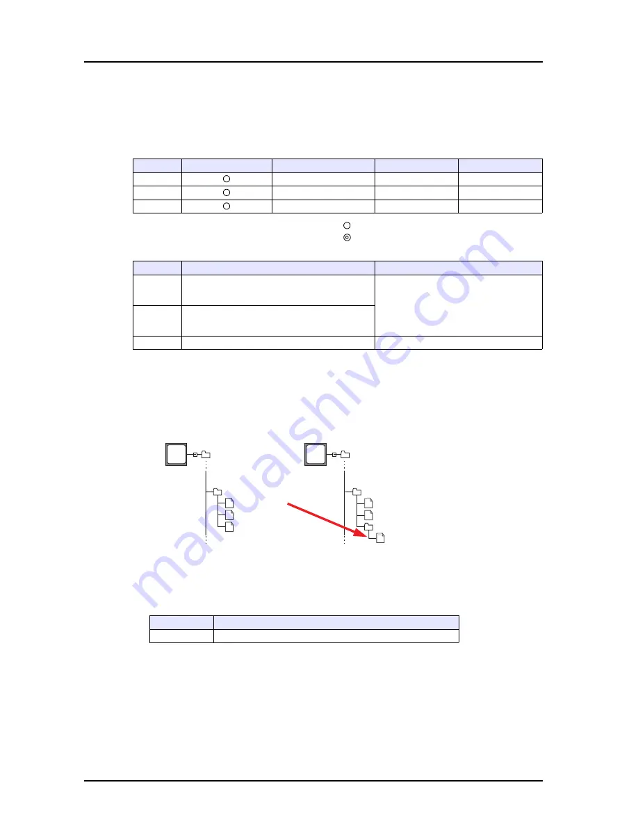
This macro command is used to move the file or folder [F0] to the path [F1].
File renaming is also possible.

Available memory

: Setting enabled (indirect designation disabled)

: Setting enabled (indirect designation enabled)

Range

Example

• Movement from “C:\DAT0000\RECIPE\REC0000.csv” to “C:\DAT0000\RECIPE\SEISAN\abc.csv”:

$u00100 = 'C:\DAT0000\RECIPE\REC0000.csv'
$u00200 = 'C:\DAT0000\RECIPE\SEISAN\abc.csv'
MOVE_FILE $u00100 $u00200

Supplementary information

• If an illegal full pathname is specified, this macro command does not work.  An error will result.
• For the V8 series, the result of macro execution is stored in $s1062.

When the execution of the macro is normally complete, the value at the address is not updated.  
Therefore, before macro execution, resetting the value at the address to zero is recommended.

• In the case of a read-only file movement between drives, the file is copied to the target location, 

and the file at the original location is not deleted.

• A folder to be moved is allowed to contain a maximum of 5 hierarchical levels under the folder.  If 

files or folders at further lower levels exist under the folder, the folder and the files/folders placed 
under it are copied to the target location, but those at the original location are not deleted.

Internal Memory

PLC1 - PLC8 Memory

Memory Card

Constant

F0
F1
F2

Value

Remarks

F0

Source full pathname (within 255 
alphanumerics)

Drive designation
A: USB-FDD drive
B: (not used)
C: Built-in CF card drive 
D: Memory connected to USB port 

F1

Target full pathname (within 255 
alphanumerics)

F2

0 fixed

Code (DEC)

Description

1

Execution error

96

MB

CompactFlash Card

RECIPE

DAT0000

REC0000.csv

REC0001.csv

REC0002.csv

96

MB

CompactFlash Card

RECIPE

DAT0000

SEISAN

abc.csv

REC0001.csv

REC0002.csv

(Drive C:)                               (Drive C:)

Move

* The  file 

“REC0000.csv” is 
deleted.

Содержание MONITOUCH V8 SERIES

Страница 1: ...Reference Additional Functions V8series...

Страница 2: ...nal functions for the version 5 3 0 0 March 2009 1060NE3 Fourth edition Additional functions for the version 5 4 1 0 December 2009 1060NE4 Fifth edition Additional functions for the version 5 4 8 0 Ju...

Страница 3: ...ini Hitachi HIDIC S10 2 S10mini Ethernet Hitachi HIDIC S10V Hitachi HIDIC S10V Ethernet Fuji Electric MICREX SX OPCN 1 Fuji Electric MICREX F Fuji Electric FALDIC series Siemens S7 PROFIBUS DP SAIA PC...

Страница 4: ...dels added for ladder transfer Allen Bradley SLC500 Models added for ladder monitor Fuji Electric SPB N mode FLEX PC CPU Fuji Electric Micrex SX Yokogawa Electric FA M3 FA M3R 5 1 0 0 1 100 1 110 V806...

Страница 5: ...BUS RTU Matsushita Electric Works FP X series SHINKO ELECTRIC SELMART DELTA TAU DATA SYSTEMS PMAC Ethernet MITSUBISHI ELECTRIC QnU CPU port July 2008 5 2 0 0 1 200 Connectable models added FANUC Power...

Страница 6: ...ix Ethernet 1 n connection TOYO DENKI GPCsx series TOYO DENKI GPCsx CPU port TOYO DENKI GPCsx series Ethernet TOYO DENKI GPCsx SX bus TOYO DENKI GPCsx OPCN 1 KEYENCE KZ A500 CPU TOSHIBA VF S7 TOSHIBA...

Страница 7: ...ow hide function Ethernet network table number increase up to No 255 Macro command SMPL_CSV2 SMPL_CSVBAK2 HDCOPY3 file name designation Backspace switch enabled for numerical data entry Scroll bar rea...

Страница 8: ...ries MITSUBISHI ELECTRIC MR J3 T SHINKO TECHNOS JCx 300 Series Shimaden Shimaden standard protocol New functions Multi link2 Ethernet available for 1 n connection using MODBUS RTU August 2009 5 4 8 0...

Страница 9: ...January 2010 5 4 11 0 1 530 Connectable models added MODBUS TCP IP Ethernet extended format OMRON KM20 OMRON KM100 Fuji Electric FVR 11S MODBUS RTU M System R1M series MODBUS RTU New functions Microso...

Страница 10: ...I ELECTRIC OMRON Ladder monitor display area adjustment to the screen size Default parts change 2D parts for item placement Multi line text property batch change for switch lamp Switch lamp text cente...

Страница 11: ...print s1009 s1011 CVFD October 2010 5 4 17 0 1 650 Connectable models added Yamatake NX CPL Yamatake NX Modbus RTU Yamatake NX Modbus TCP IP RKC FB100 FB400 FB900 MODBUS RTU Fuji Electric FRENIC5000G1...

Страница 12: ...for entry targets Ladder monitor MITSUBISHI ELECTRIC QnA series link MITSUBISHI ELECTRIC QnA series Ethernet V808CH brightness adjustment macro command BRIGHT supported GE Fanuc 90 series SNP X multi...

Страница 13: ...e information in this manual are subject to change without prior notice 4 If the specifications of the software do not correspond with the contents of this manual the software specifications have prio...

Страница 14: ...V8 Series Operation Manual 1058NEx The information related to the operations of the V SFT version 5 such as software composition editing procedure or limitations is explained in detail V8 Series Hardw...

Страница 15: ...C V808C V808iCH V808CH V806iT V806iC V806iM V806T V806C V806M 2 Overlap Superimpose Video overlap 3 Switch Coordinate output for analog only Transparency Multi output Delay Message box 4 Lamp Transpar...

Страница 16: ...mensional Two dimensional 18 CF card Built in USB 2 drive connection 19 Ethernet function Screen data transfer PLC connection 2 2 2 E mail Web server A1 Buffering area Store target SRAM Store target C...

Страница 17: ...h Numerical data entry extended 7 Graph real values Panel meter function extended 1 1 1 1 3 1 3 1 3 1 3 1 2 3 4 1 2 3 4 8 Trend graph real values Trend sampling Graph show hide function 9 Alarm functi...

Страница 18: ...the target screen Memory batch change Selection order batch change Image file 3D part conversion Cross reference Text comparison Selective transfer Message comment transfer 26 USB barcode reader USB...

Страница 19: ...the power is on Otherwise electric shock may occur You must put a cover on the terminals on the unit when you turn the power on and operate the unit Without the terminal cover in place electric shock...

Страница 20: ...g resistance less than 100 Otherwise electric shock or fire may occur Prevent any conductive particles from entering the MONITOUCH Failure to do so may lead to fire damage or malfunction After wiring...

Страница 21: ...er which is commercially available If a data receive error occurs when MONITOUCH and the counterpart PLC temperature controller etc are started at the same time read the manual for the counterpart uni...

Страница 22: ...1 10 2 Global Overlap Overview 2 1 Global Overlap Setting Dialog 2 2 Main Tab Window 2 2 Detail Tab Window 2 4 Showing Hiding Global Overlap Display 2 5 Internal Command 2 5 External Command 2 6 Funct...

Страница 23: ...tch Area 6 5 6 2 Slider Switch Overview 6 6 Setting Procedure 6 7 Setting Dialog 6 7 6 3 Numerical Data Entry Numeral Insertion DELETE Keys Enabled Overview 6 9 Display During Data Entry 6 9 Examples...

Страница 24: ...2 Setting Items 9 2 Buffering Area Setting 9 3 Message Edit 9 7 Limitations 9 9 9 2 Acknowledge Function Overview 9 10 Applicable Items 9 11 Setting Items 9 11 Alarm Tracking 9 11 Buffering Area Sett...

Страница 25: ...Multi language Editing Function Multi language Batch Change 13 16 Overview 13 16 Setting Procedure 13 16 Multi language Batch Copy 13 19 Overview 13 19 Setting Procedure 13 20 Multi language Editing...

Страница 26: ...t View 15 7 Right click Menu or Display Environment 15 8 Examples 15 9 Memory Designation Bit Designation 15 9 Memory Designation Word Designation 15 10 Display Order 15 11 16 FTP Server Overview 16 1...

Страница 27: ...tting 18 2 18 2 V SFT Setting Network Camera Display Setting 18 3 Network Camera Display Dialog 18 4 Main Tab Window 18 4 Detail Tab Window 18 5 Switches 18 6 18 3 Axis Network Camera Example Axis 214...

Страница 28: ...mote Desktop Window 19 15 Switch to Show Hide Remote Desktop Window 19 18 Macro Command to Show Hide Remote Desktop Window 19 20 19 5 Remote Desktop Window Configuration and Operation Window Configura...

Страница 29: ...New Database 20 35 Creating a New Table 20 36 Opening a Table 20 39 20 6 Data Source ODBC Setting 21 Operation Logs 21 1 Operation Log Function Overview 21 1 Setting 21 3 Location for Setting 21 3 Set...

Страница 30: ...c 23 3 Conversion 23 13 Comparison 23 25 CF Card Sampling 23 27 CF Card Others 23 31 24 Tag 24 1 Overview Address Designation 24 1 Variable Designation 24 2 Array 24 2 24 2 Tag Editing Structure of Ta...

Страница 31: ...version Overview 25 17 Applicable Items 25 17 Setting Procedure 25 18 Placing Parts from the Tool Menu 25 18 Placing Parts with Copy Paste 25 22 Note 25 25 25 5 Cross reference Overview 25 26 Setting...

Страница 32: ...inter Shape 26 11 Mouse Operation 26 11 Limitations 26 11 26 6 USB FDD Floppy Disk Drive Overview 26 12 Connection 26 12 Setting Procedure 26 13 Applicable Media 26 13 Available Functions 26 13 Macro...

Страница 33: ...0 OMRON CX Programmer 27 10 Panasonic FPWIN GR 27 10 Yokogawa Electric Wide Field2 27 10 Fuji Electric SX Programmer Expert D300win 27 11 Notes 27 11 Appendix 1 System Memory Addition to System Memory...

Страница 34: ...not allowed None CF D sub Analog switch V806T V806C Unchecked V806iM V806M Checked None 16 gray scales V806M Unchecked Item V806iT V806T V806iC V806C V806iM V806M Display device TFT color STN color ST...

Страница 35: ...t available with the following functions bit order alarming alarm sub display time order alarming alarm logging message mode data sampling alarm tracking and memory card For any parts which are not re...

Страница 36: ...Color w o blinking 32K Color 128 Color None Analog switch Matrix switch V810C Unchecked V808iC V808C Checked Analog switch V808C Unchecked Item V810iC V810C V808iC V808C Display device TFT color Disp...

Страница 37: ...al center on V808CD Therefore the EL type MONITOUCH can easily be substituted by V808CD without the need to change the layout of the screen data When the EL type MONITOUCH is substituted by V808CD the...

Страница 38: ...08C 1 Click File Open The Open dialog is displayed 2 Select 80 for Files of type Then select the screen data of GD 80E and click Open 3 The Edit Model Selection dialog is displayed Select options as s...

Страница 39: ...displayed on V SFT Unchecked On the V8 screen data is displayed in the same position as specified on V SFT Color Batch Change Checked Converts any colors other than black into the color specified her...

Страница 40: ...1 1 Edit Model Selection 1 7 1 For pattern data there are some colors that cannot be converted In such a case the dialog shown below is displayed 5 Click OK after setting...

Страница 41: ...ardware Specifications Manual Model Edit Model Size Color Memory Expansion Touch Switch V815iX V815X 1024 768 64K color w o blinking 32K color None Analog switch Item V815iX Display device TFT color D...

Страница 42: ...Edit Model i Series Size Color Memory Expansion Touch Switch V808iCH V808CH Checked 640 480 64K color w o blinking 32K color 128 color None Analog switch V808CH Unchecked Item V808iCH V808CH Display...

Страница 43: ...ry disconnection Unchecked default Formatting the SRAM is executed on the Main Menu screen while the battery is connected with the V8 unit Checked A forced formatting is executed Whether an automatic...

Страница 44: ...ipe mode item is updated The recipe mode item is reset to the default status If editing is disabled by the command memory the current display status is kept Return switch prohibited when switching the...

Страница 45: ...minimum values for alarm are set in the range according to After range change Alarm maximum value u1000 100 Checked The maximum and minimum values for alarm are set in the range according to Before r...

Страница 46: ...he global overlap display is set the overlap display remains displayed even when the screen is changed 1135 120 1564 554 1653 10 23 9 89 7 23 11 02 12 03 849 988 489 156 484 5548 6615 4485 9981 1165 8...

Страница 47: ...ap 2 2 Global Overlap Setting Dialog Click System Setting Global Overlap Setting and check Use Overlap The global overlap display works as overlap ID No 3 Main Tab Window The global overlap ID number...

Страница 48: ...op memory address n is used n to n 3 Overlap Library No This is valid only when External is selected for Designate A memory address of Info Output Memory n 1 is automatically allocated Specify the ove...

Страница 49: ...mory n 3 Y coordinate Unchecked The overlap display is shown in the same position as it is placed for the overlap library Command Memory Checked Specify one word of memory as desired This is used for...

Страница 50: ...er to the Macro Reference Manual Function Description Multi Overlap Display Select to show the global overlap display Overlap ID 3 cannot be changed Overlap Library No Specify the desired number Displ...

Страница 51: ...lap display can be shown or hidden by using the command memory 1 Specify the overlap library number for Overlap Library No 2 Check Command Memory in the Detail tab window in the Global Overlap Setting...

Страница 52: ...the area where the cursor can move The content is shown below 2 Entry area Select the area where the cursor can move between the data fields to select an entry target 0 Disabled The cursor moves in t...

Страница 53: ...SB 2 Entry area designation 1 Order INC designation 0 to 255 4 Write enabled disabled 0 Write disabled 1 Write enabled 3 Entry target data selection 0 Data display 1 Table data display Bit No Type 13...

Страница 54: ...s V 1561 Display position X coordinate V 1562 Display position Y coordinate V 1563 Overlap library number No 0 to 9999 Not displayed 1 V Bit No Type 12 11 10 Data Display Data Block 0 0 0 Base Data bl...

Страница 55: ...e For V810T Model Maximum Screen Size Maximum Overlap Size Maximum Overlap Size for Video V815iX 1024 768 786 432 3 145 728 1 572 864 The total of widths of four overlap displays must not exceed 2 048...

Страница 56: ...en executed to change the language The item placed on the global overlap display has been shown hidden The offset memory value of the item placed on the global overlap display has been changed The ove...

Страница 57: ...2 Global Overlap 2 12 Please use this page freely...

Страница 58: ...unction switch setting discussed hereafter a switch can easily be capable of two functions Targeted Switches Switches with the following setting Under Function in the Switch dialog Entry and Write or...

Страница 59: ...sible to produce a continuous sound while a switch is held down Location for Setting 1 Click the target switch Its Switch dialog is displayed 2 Open the Detail tab window Check Buzzer Sound and select...

Страница 60: ...ified range is set on MONITOUCH the lamp display is not changed OFF ON P3 P4 P5 P6 P128 P127 P8 P7 Pattern 0 Operation Stop Pattern 1 Pattern 2 Pattern 3 Pattern 4 Pattern 5 Operation Start Tank Error...

Страница 61: ...cant bit is displayed M000 015 M016 031 M112 127 M000 015 M016 031 M112 127 Status Monitor Screen Operation Stop Status Monitor Screen Pressure Drop Set ON for M4 in the PLC memory Pattern 5 P6 is dis...

Страница 62: ...ith word designation is explained Step 1 Click on the lamp part placed on the screen to display the item dialog Select Word for Memory Designation and BCD or DEC for Input Type Step 2 In the Style tab...

Страница 63: ...layed For the setting procedure refer to the procedure for word designation mentioned above In the Text tab window register the text for each pattern If you cannot select a tab window other than 0 sel...

Страница 64: ...cheduled production volume non defective count and defective count for a machine selected from Nos 1 to 3 2 written to the offset value designation memory D100 Numerical data display Machine number D1...

Страница 65: ...ory Specify a memory location as the base offset memory 2 Offset Value Designation Memory Specify a memory location to store the offset value for the base memory and either code DEC or BCD It is possi...

Страница 66: ...locations refer to the V8 Series Operation Manual When the screen is updated the offset value designation memory is read for the items placed on the screen For a screen including multiple offset valu...

Страница 67: ...er of bytes text color background color Attribute specification memory is not available with table data display data sampling graphic library and data sheet but available with expanded data sheet 31 5...

Страница 68: ...or reading the attribute specification memory This selection is commonly applied to all attributes Num Display dialog The attributes checked in these dialogs will be displayed according to the values...

Страница 69: ...the number of digits an overflow arises For HEX OCT or BIN as Display Type decimal point setting does not take effect Even if a value is set for Decimal Point in such a case it is assumed to be zero D...

Страница 70: ...on Palette 1 in the Custom Color dialog Colors correspond to the following color codes 31 5 Foreground color 15 14 13 12 11 10 9 8 7 6 5 4 3 2 1 0 0 127 colors Foreground color Blinking 0 No 1 Yes n C...

Страница 71: ...display has become higher than the maximum or lower than the minimum specified for alarm the value is shown in the color preset for alarm When Attribute Specification Memory is checked in the Num Disp...

Страница 72: ...as a switch for calling a keypad registered on the Multi Overlap dialog 120 1564 554 1653 988 489 156 484 988 489 156 484 120 1564 554 1653 9 8 7 6 5 4 CLR 3 2 1 ENT 0 Pressing on a numerical data di...

Страница 73: ...et must be selected Setting Procedure The procedure is explained with an example of a numerical data display part Step 1 Select Entry Target for Function of the numerical data display part placed on t...

Страница 74: ...has been completed an overlap icon for multi overlap is displayed in addition to the numerical data display on the screen Overlap ID 1 Specify the overlap ID to be used for showing the keypad Overlap...

Страница 75: ...you uncheck the box for With Entry Key of a numerical data display or character display part or if a function other than Entry Target is selected for Function the confirmation dialog shown below will...

Страница 76: ...w Switch Area The data display with entry function has a switch area The switch area will be displayed with dotted lines when you select Display Environment Display and check the box for Display Area...

Страница 77: ...finger from the slide switch a value is written and the slide switch is moved at the same time Display for slide switch movement While you are moving your finger to move the slide switch only a line i...

Страница 78: ...ch on the Parts List window that is displayed by selecting Parts Parts List Setting Dialog Main tab window Memory Specify a memory address to be changed by the slider switch Data Length 1 Word 2 Word...

Страница 79: ...of the rail If the size of the rail is smaller than the number of divisions the rail is divided into the number defined in the case where Define detent steps by the size of the item is checked Scale...

Страница 80: ...part A numeral insertion is made to the right of the cursor When numerals exist at all places entering a new numeral deletes the leftmost numeral Additionally entering a numeral at the leftmost place...

Страница 81: ...to 6 Press the 2 key The rightmost numeral 0 of the fractional part is deleted and 2 is placed at the left of the cursor The display shows 1 526 Example Overwriting the rightmost numeral 7 to show 1...

Страница 82: ...tting is reflected throughout the entry mode for all screens 1526 126 9 7 8 6 4 5 3 1 2 ENTER 0 CLEAR DELETE BackSpace 9 7 8 6 4 5 3 1 2 ENTER 0 CLEAR DELETE BackSpace 1 526 1 560 9 7 8 6 4 5 3 1 2 EN...

Страница 83: ...key does not delete the leftmost numeral of the whole number part as well as the tenth place of the fractional part When a numeral is deleted from the whole number part the cursor remains in the same...

Страница 84: ...or maximum scale value target value or alarm falls outside the permissible range of MONITOUCH the number cannot be displayed For more information on the permissible range refer to the V8 Series Refere...

Страница 85: ...tion The design of the scale or indicator can be changed to the desired one by using a bitmap file etc Numerical Data Display The current data can be displayed on the panel meter in numerical form 0 5...

Страница 86: ...V8 Models Not available on the portrait orientated V806 Contents Model Color V815iX V812 i S V810 i S V810 i TV808 i S V810 i C V808 i C V808 i CH V806 i T V806 i C V806 i M Alarm 2 64k colors 32k co...

Страница 87: ...nge overlaps with another the color of the greater number comes to the fore Range Set the color to display for the value outside the range specified for data attributes No of Divisions 1 16 Set the nu...

Страница 88: ...r indicator can be changed to the desired one by using a bitmap file etc For more information refer to Customizing the Indicator and Scale page 7 10 Style Indicator Set the indicator color When Alarm...

Страница 89: ...lected bitmap file is stored in V SFT 5 Parts User For the detailed procedure refer to Customizing the Indicator and Scale page 7 10 Unchecked sector Checked complete round circle Graph area Start Ang...

Страница 90: ...ator Setting Extension 2 Check this box to change the indicator part A desired bitmap file can be used Start Point Select a shape of the top and end of the indicator End point Length Specify the lengt...

Страница 91: ...Meter Extended 7 8 Scale Direction Inside Outside Select the position of the scale inside or outside of the outer circle Color Set the scale color Radius Set the scale radius Inside Outside Scale Sca...

Страница 92: ...ize Check this box when using a desired bitmap file for the scale design For more information on the setting refer to Customizing the Indicator and Scale page 7 10 No of Divisions 1 255 Example No of...

Страница 93: ...fixing the ratio between the width and height Panel Meter Center Point The coordinate values of the panel meter circle center point are displayed Base Point X Base Point Y Specify the X or Y coordina...

Страница 94: ...he procedure for importing a bitmap image into the panel meter Scale Black code 0000 in the bitmap image automatically becomes transparent on MONITOUCH Indicator scale_A bmp back_A bmp pin_A bmp Backg...

Страница 95: ...s and Inner radius in the Style tab window Step 4 Import a bitmap image of the indicator Select Indicator Setting Extension Customize on the Style tab window in the Panel Meter dialog and check Use Cu...

Страница 96: ...Import a bitmap image of the scale Select Show a scale Customize in the Scale tab window in the Panel Meter dialog and check Use Custom Bitmap Press the Open button and select a bitmap file Example s...

Страница 97: ...data display is used to show a measurement value in numerical form on the panel meter Main Tab Window Digits Specify properties of the numerical data display For more information refer to the V8 Seri...

Страница 98: ...ng a desired bitmap file for the design of the numeric data display Black code 0000 on the image automatically becomes transparent on MONITOUCH To display black specify a color approximate to black Se...

Страница 99: ...r center point are displayed Base Point X Base Point Y Specify the X and Y coordinate values of the base point on the numerical data display Default Resets the X and Y coordinate values of the base po...

Страница 100: ...de the range specified for Scale in the Main tab window However when the number of digits exceeds the specified value is displayed MONITOUCH Model Max Size of Panel Meter unit dots V815iX Height 768 w...

Страница 101: ...7 2 Panel Meter Extended 7 18 Please use this page freely...

Страница 102: ...a included the number cannot be displayed For more information on the permissible range refer to the V8 Series Reference Manual If real data set for trend sampling or data sampling exceeds the permiss...

Страница 103: ...ary depending on the operating conditions Applicable Items Trend sampling Setting Items Use Control Memory in the Trend Sampling dialog page 8 3 For trend sampling setting instructions refer to the Re...

Страница 104: ...ord designation This memory address is associated with showing or hiding graph line Nos 0 15 Each graph line is shown and hidden when the corresponding bit is set ON and reset OFF Process Cycle High S...

Страница 105: ...Memory is not checked the update timing depends on High Speed for Process Cycle When Use Control Memory is set this setting is counted as one of the number of memory locations that is permitted for o...

Страница 106: ...ch alarm relevant data will help you locate and investigate the causes of alarms Touch YAMADA SATO MJ1 F 1 F 2 F 3 F 4 F 5 F 6 F 7 SYSTEM 65 0 A B Thermal error Material shortage The corresponding ala...

Страница 107: ...ion in conjunction with the use of alarm tracking Alarm display example when Record Parameters is not checked Alarm display example when Record Parameters is checked Temperature rise of Tank A 65 C 08...

Страница 108: ...rs For the determination of the size of the primary storage refer to Buffer size calculation for the use of parameters and the alarm acknowledge function page 9 17 2 Check Record Parameters Record Par...

Страница 109: ...selection under Display Type Parameter Yes None Select either option for each message Double clicking the box under Parameter calls up the Parameter Table dialog Shows the selected message Adds a new...

Страница 110: ...Input Format Select the code to be used at the time of data reading DEC BCD FLOAT Display Format Select the format of the data to be displayed DEC w o sign DEC with sign DEC with sign HEX OCT BIN bin...

Страница 111: ...9 1 Parameter Addition Function 9 6 5 When the settings have been completed in the Parameter Table dialog click OK to close it...

Страница 112: ...9 1 Parameter Addition Function 9 7 9 Message Edit 1 Double click the area enclosed in the red box as shown below 2 The Message Edit window is displayed...

Страница 113: ...registered in the Parameter Table dialog specify those numbers in the Message Edit window PxS Specify a parameter No 0 to 7 as registered in the Parameter Table dialog Go to the Parameter Table dialo...

Страница 114: ...played If Total Frequency of Occurrence Display or Total Time of Occurrence Display is selected for alarm history display the parameter symbols in alarm messages are displayed as If changes are made t...

Страница 115: ...ESET 08 30 45 10 45 18 10 51 32 2 Roller error 1 Sensor error DW UP DEL RET RESET 11 32 01 11 32 01 Acknowledge All Occurrence time The color of all the messages turns to the color for acknowledgement...

Страница 116: ...ge 9 11 Buffering area page 9 14 Message edit Refer to the Reference Manual Acknowledge switch page 9 15 Alarm Tracking 1 Go to the Alarm Tracking dialog and open the Main tab window 2 Check the box f...

Страница 117: ...34 00 2 Roller error 1 Sensor error 2 Sensor error 1 Roller error Occurrence Confirmation Time Confirmation Time Occurrence time When there are messages which are not acknowledged yet asterisks are di...

Страница 118: ...Reset Acknowledge Occurring Acknowledge After Reset Four colors can be set to display alarm messages depending on the status Unacknowledged Occurring 2 Select a color used to display an occurring alar...

Страница 119: ...ction 9 14 Buffering Area Setting 1 Select System Setting Buffering Area Setting Others 2 Check the box for Alarm Acknowledge function Alarm Acknowledge function Check this box when using the alarm ac...

Страница 120: ...nction Description Acknowledge Alarm acknowledged times can be displayed in the alarm tracking area Selective Acknowledge For a selected alarm message this switch is used to acknowledge the message an...

Страница 121: ...reset afterwards the message turns green When the Acknowledge All switch is pressed the color of the occurring alarm message changes from black to red Once the alarm is reset the message color change...

Страница 122: ...knowledged time is not displayed Buffer size calculation for the use of parameters and the alarm acknowledge function The size of the primary storage can be calculated with the equations below A Numbe...

Страница 123: ...9 2 Acknowledge Function 9 18 Please use this page freely...

Страница 124: ...f 5 4 8 0 or later touch switch operation becomes possible for the two computers at the same time by using modular jacks MJ1 MJ2 You can operate each computer on MONITOUCH according to different purpo...

Страница 125: ...ows 98 95 NT4 0 2000 Me 2000 XP Touch panel driver settings For more information on the touch panel driver refer to Chapter 14 in the V8 Series Reference Manual provided separately V SFT Setting How t...

Страница 126: ...Use Default Comm Parameter Setting Limitations When the touch switch emulation of the RGB display function and the remote desktop window display function are used at the same time a USB mouse cannot...

Страница 127: ...10 RGB Display touch switch emulation 10 4 Please use this page freely...

Страница 128: ...the rail is pressed When you remove your finger from the slide switch or the rail a value is written and the slide switch is moved at the same time Display for slide switch movement While you are mov...

Страница 129: ...arts Parts List to display the Parts List window Select Scroll Bar in the drop down list Select a part and drag it onto the screen with the mouse Item Scroll direction JPEG display Vertical and horizo...

Страница 130: ...Part Modify Part The dialog shown below is displayed Select Edit a rail or Edit a slider Direction UP DW RGT LFT Select a sliding direction Edit Parts Rail Slide Rail Slide Select the part whose desig...

Страница 131: ...ows and columns as displayed can be scrolled in units of a row or a column If multiple scroll bars provided with the same ID which do not link to items are placed the scroll bar at the front takes eff...

Страница 132: ...arts placement irrespective of the grids thereby diversifying layouts on data sheet screens Those data sheets can be printed out in color Applicable Printer Models PictBridge compatible printer A 350...

Страница 133: ...ake the following settings in the Printer tab window Type PictBridge Use Extension Data Sheet checked You may go to the Data Sheet Setting dialog in another way by clicking Registration Item Data Shee...

Страница 134: ...ridge only on USB B port Check this option when using the USB B port for connection with the PictBridge printer during the RUN mode of MONITOUCH Switch the MONITOUCH display to the Main Menu screen at...

Страница 135: ...tion of Expanded Data Sheet Screen When creating a data sheet screen click Registration Item Data Sheet A maximum of 1 024 screens can be registered Background in white only Paper Size A4 Landscape Pr...

Страница 136: ...meter Statistic bar graph Statistic pie graph Time display Calendar Line continuous line Box Circle Text multi text Dot Paint Scale Pattern Line Box Circle Text Dot Paint Scale Pattern Library Frame...

Страница 137: ...ted 3 Set bit 9 of read area n 1 0 1 4 Data sheet is printed With the Macro Command The macro command SYS STA_LIST is available to print data sheets Available memory Setting enabled indirect designati...

Страница 138: ...ed to an expanded data sheet screen For parts placed on an expanded data sheet screen the setting with Display Setting takes effect When a part should always be printed select Show for Display Setting...

Страница 139: ...and print size cannot be changed Margins to be left will slightly vary among different printer models How to correct printer errors depends on the printer models For more information refer to the inst...

Страница 140: ...be used on the MONITOUCH 1 Font selection Select the desired font from Bitmap font Gothic font and Stroke font first For the information on the differences among fonts refer to the next section 2 Sett...

Страница 141: ...to the MONITOUCH the required memory capacity is larger than that of bitmap fonts while the displayed typeface has smoother lines In the case of Gothic fonts depending on the function assigned to the...

Страница 142: ...ont Setting 13 3 13 Font Setting Procedure Follow the steps below Step 1 Select System Setting Font Setting The Font Setting dialog is displayed Step 2 Choose the font type for Font Choose Bitmap font...

Страница 143: ...the editor is started for the first time Japanese 32 is displayed Step 4 To change to another language double click on Language 1 English Western Europe or click on Language 1 English Western Europe...

Страница 144: ...Font Setting 13 5 13 Step 5 The dialog shown below is displayed Select the desired font from the drop down list and click OK Choose Chinese Simplified here Step 6 When the font has been selected clic...

Страница 145: ...guage name and press the Setting button A dialog is displayed Select the desired bitmap font from the drop down list and click OK When creating multi language screens using bitmap fonts select from th...

Страница 146: ...8 to 20 points may look rigid compared with those of greater point sizes Point size specification can make your screen configuration easier Applicable Models V812 V810 V808 64k colors 32k colors Stro...

Страница 147: ...nish Faeroese French CP1252 code Chinese Traditional stroke Chinese traditional English BIG5 code A141 to F9FE ASCII code Chinese Simplified stroke Chinese simplified English GB2312 code A142 to F7FE...

Страница 148: ...nt Setting dialog For more information refer to Transfer Font Setting page 13 14 Font Main Menu screen Japanese stroke JAPANESE STROKE English Western Europe stroke ENGLISH STROKE Chinese Traditional...

Страница 149: ...13 2 Stroke Fonts 13 10 Font Setting Step 1 Select System Setting Font Setting The Font Setting dialog is displayed Step 2 Choose Stroke font for Font...

Страница 150: ...is displayed for Language 1 Step 4 To change to a stroke font of another language double click on Language 1 Japanese stroke or click on Language 1 Japanese stroke and then click the Setting button C...

Страница 151: ...ct the desired stroke font from the drop down list and click OK Step 6 When the font has been selected click OK If you change from a non stoke font to a stroke font the message shown below will be dis...

Страница 152: ...he language name or click the language name and press the Setting button A dialog is displayed Select the desired stoke font from the drop down list and click OK When creating multi language screens u...

Страница 153: ...MONITOUCH If you select the necessary fonts the interface language can be switched without using the CF card The more fonts selected for transfer the less the capacity for screen data becomes availabl...

Страница 154: ...ypefaces are not available Points Remarks 8 One byte 6 11 dots two byte 11 11 dots 9 One byte 6 12 dots two byte 12 12 dots 10 One byte 7 13 dots two byte 13 13 dots 11 One byte 8 15 dots two byte 15...

Страница 155: ...ng Procedure This section explains the procedures for batch change taking the following case for an example Screen No 1 Example Changing the properties of the text on the switches Language 2 English W...

Страница 156: ...g dialog to be displayed check Screen and specify screen Nos 1 and 2 as the range Also go to the Target Item area check Select and press the Detail button In the Changed Item Setting dialog to be disp...

Страница 157: ...nguage Editing Function 13 18 Step 5 Review the settings made in the previous steps and click OK The following dialog is displayed When you are sure about the message click Yes Changing the properties...

Страница 158: ...pically needed to enter or copy each of those characters or numbers one by one for placing them on screens in different languages The function of multi language batch copy discussed in this section en...

Страница 159: ...data Select Tool Multi Language Batch Change Multi Language Batch Copy The Multi Language Batch Copy dialog is displayed Step 2 Batch copy in this example targets all the text and switches in languag...

Страница 160: ...this example targets all properties Go to the Setting on Changes area and check All Step 5 Review the settings made in the previous steps and click OK The following dialog is displayed When you are su...

Страница 161: ...e 1 Japanese Language 2 English Western Europe Language 3 Chinese Simplified Language 1 English Western Europe Language 2 Chinese Simplified Language 3 Japanese 32 Language 1 Japanese 32 Language 2 En...

Страница 162: ...13 23 13 Step 2 To change language 1 to Chinese Simplified select Language 2 Chinese Simplified in the drop down list for Language 1 Step 3 To change language 2 to Japanese select Language 3 Japanese...

Страница 163: ...to English Western Europe select Language 1 English Western Europe in the drop down list for Language 3 Step 5 Check the settings and click OK The dialog shown below is displayed If the settings are...

Страница 164: ...t program Earlier than version 5 1 0 0 1 Change the file extension csv to txt 2 Translate the text as an encoded text on Word and save the file 3 Change the file extension txt to csv From this new ver...

Страница 165: ...r Import button The Save As dialog or Open dialog is displayed txt is selected for Save as type If you do not want to save into a Unicode text file but a csv file select csv for Save as type Step 3 Cl...

Страница 166: ...cedure Exported Unicode text files can be edited on Excel When editing follow the steps below Step 1 Start Excel Step 2 Select the Unicode text file you have exported and drag and drop the file on Exc...

Страница 167: ...ep 4 Edit the text as desired In the example below Chinese simplified is input Step 5 To save the file select File Save As The Save As dialog is displayed Step 6 Select Unicode Text txt for Save as ty...

Страница 168: ...s fonts 3D parts If you store data for the items that would occupy a large memory space such as Windows fonts or 3D parts on a CF card you can reduce the MONITOUCH memory space required for elaborate...

Страница 169: ...creen data Step 2 Check the box for Range of Screen to be Saved to CF Card Specify the start screen number and the end screen number to be saved on a CF card Screens must be selected in consecutive nu...

Страница 170: ...ck File Write to CF Card The Write to CF Card dialog is displayed Step 5 If the screen data is being edited check the box for Write Data Being Edited If the screen data is not being edited uncheck the...

Страница 171: ...e error message Screen No Error will be displayed SCRN Folder The SCRN folder contains the following files In addition to the folder shown above the DSP0000 BIN file stored in the DSP folder is also r...

Страница 172: ...iginal data file it is necessary to convert DSP0000 BIN in the DSP folder Follow the steps below Step 1 Start V SFT Step 2 Select File CF Card Manager The dialog for specifying the CF card drive is di...

Страница 173: ...tting dialog select System Setting CF Card Setting are not displayed in this list Check the data size before setting the CF Card Setting dialog The screen BIN data stored on a CF card may take longer...

Страница 174: ...oring Windows Fonts Setting Procedure Store Windows fonts on a CF card as shown below 1 Editor settings Step 1 Select System Setting CF Card Setting The CF Card dialog is displayed Step 2 Check the bo...

Страница 175: ...data to a CF card This is the same as writing ordinary screen data Step 1 Start V SFT Step 2 Select File CF Card Manager The dialog shown below is displayed Step 3 Specify the drive where the CF card...

Страница 176: ...te to CF Card dialog is displayed Step 5 If the screen data is being edited check the box for Write Data Being Edited If the screen data is not being edited uncheck the box for Write Data Being Edited...

Страница 177: ...TOUCH than those stored in the MONITOUCH memory Please keep such a time lag in mind Storing 3D Parts Setting Procedure Store 3D parts on a CF card as shown below 1 Editor settings SCHEADER BIN Header...

Страница 178: ...4 11 14 2 Writing data to a CF card This is the same as writing ordinary screen data Step 2 Check the box for Store 3D Parts in CF Card Step 3 Click OK Step 1 Start V SFT Step 2 Select File CF Card Ma...

Страница 179: ...Click File Write to CF Card The Write to CF Card dialog is displayed Step 5 If the 3D part is being edited check the box for Write Data Being Edited If the 3D part is not being edited uncheck the box...

Страница 180: ...tains the following files Notes The 3D parts stored on a CF card may take longer before the 3D parts appear on the MONITOUCH than those stored in the MONITOUCH memory Please keep such a time lag in mi...

Страница 181: ...at on a CF card the messages in TXT file format can be edited anywhere without the dedicated editor and in addition the MONITOUCH memory space is saved Note that however the TXT file must be saved on...

Страница 182: ...etting has been made click OK and save the screen data file TXT files must be prepared manually separately Create files under the filenames shown below and store them in the MSG folder on the CF card...

Страница 183: ...es on the MONITOUCH MSG Folder Store the following files in the MSG folder Notes If both text files MSGxxyyy BIN conventionally used and MSGxxyyy TXT available from this version exist in the same MSG...

Страница 184: ...er in the header line The titles of the sampling data items do not appear However when you create a CSV file for titles and store it on the CF card beforehand sampling data converted to CSV format sho...

Страница 185: ...le for titles Name a CSV file for tiles as designated below and store it in the SAMPLE folder on a CF card BITMAP SRAM CARD DSP FONT HDCOPY JPEG RECIPE SAMPLE SNAP WAV WEBSERV DAT0000 MEMO SCRN MSG SM...

Страница 186: ...the following file in the SAMPLE folder Notes There is no limitation to the number of rows and columns in a CSV file for titles named SMHxxxx CSV A CSV file for titles must be within 239 KB in size SM...

Страница 187: ...14 3 Addition of Titles to a CSV File Sampling Data 14 20 Please use this page freely...

Страница 188: ...n advance and set them with the hide attribute which will make your future expansion easier PLC 10 23 9 89 7 23 11 02 12 03 A B C D E No 1 No 2 No 3 No 4 No 5 10 23 9 89 7 23 11 02 12 03 849 988 489 1...

Страница 189: ...ions Screen overlap library screen library data block Setting Procedure Setting Position For parts Make the setting on the Display Setting tab window in the item dialog Switch Lamp Numerical data disp...

Страница 190: ...low When the condition is satisfied the item will be shown or hidden Bit Designation The item is shown or hidden according to the activation at the specified bit memory address Bit ON Item shown Bit O...

Страница 191: ...w Redraw the section When Redraw the section is checked the screen is redrawn each time the specified memory status changes If the relevant item is registered on the screen the screen will be redrawn...

Страница 192: ...mand transfer PLC type universal serial screen If you do not want to execute these operations at the time of redrawing check the boxes as required Prohibition of screen redrawing When Redraw the scree...

Страница 193: ...Screen Setting dialog for the overlap library is displayed Determine overlap library operations to be performed at the time of screen redrawing Blinking during Screen Redrawing When the screen is bei...

Страница 194: ...h item on the editor Item List View Click View View Item List or click the Item List icon The Item List view is displayed The items set as other than Show for the show hide attribute are shown in gree...

Страница 195: ...de items The items set as Memory Designation or Hide on the Display Setting tab window of the item dialog will disappear from the screen Display Environment When Hide Items not displayed is checked on...

Страница 196: ...ars as shown below 3 When the PLC sets M200 to ON a character display appears as shown below ABCDEFGH 1234 Numerical data display Display Setting Memory Designation Bit Designation PLC Memory M100 Cha...

Страница 197: ...D200 9999 with D100 1234 another switch appears as shown below A B Switch Display Setting Memory Designation Word Designation Display Type DEC Condition 1 1234 D100 Condition 2 None Switch Display Set...

Страница 198: ...re updated every cycle or those with status change will be displayed on top M101 ON B A B C B C M100 ON M102 ON A B C Switch A Display Setting Memory Designation Bit Designation PLC Memory M100 Switch...

Страница 199: ...15 Item Show Hide Function 15 12 Please use this page freely...

Страница 200: ...ol included with Windows is available for data writing to reading from and editing in a CF card without the need for installing any special tool Available V8 Models The V8 series is equipped with a bu...

Страница 201: ...em Description Location for Setting Protocol TCP IP User name 1 to 12 one byte alphanumeric characters case sensitive Editor Password 1 to 8 one byte alphanumeric characters case sensitive Editor Port...

Страница 202: ...freeware Command Name Function Refer to cd Changes the current directory close Disconnects the connection dir Displays the file information page 16 13 ls Displays folder and file names page 16 14 put...

Страница 203: ...e specified for Input Supervisory Period the V8 automatically disconnects the connection User Name 1 to 12 one byte alphanumeric characters case sensitive Password 1 to 8 one byte alphanumeric charact...

Страница 204: ...JPEG JP00000 JPG C DAT0000 RECIPE TEST TYPE0421 CSV Drive name Maximum number of characters for a path 255 one byte characters including and an extension Maximum number of characters for a path 255 o...

Страница 205: ...for which the FTP Server Setting is finished to MONITOUCH the V8i series 2 Connect your computer to MONITOUCH via Ethernet 3 Insert a CF card into MONITOUCH and set the unit to the RUN mode With the...

Страница 206: ...ed in the FTP Server Setting dialog Press the Enter key Step 4 The following message appears Key in the password that is the same as specified in the FTP Server Setting dialog Press the Enter key The...

Страница 207: ...message is displayed If a wrong password is entered the following message is displayed If you enter the correct command after the occurrence of an error the error message remains In order to proceed...

Страница 208: ...Enter the FTP command in the Address field Key in ftp user name password MONITOUCH IP address Press the Enter key When you use Explorer or Internet Explorer key in ftp user name password MONITOUCH IP...

Страница 209: ...16 10 Step 3 The computer displays Explorer as the following Login has been completed Step 4 In Explorer you can view the contents of the CF card inserted into MONITOUCH Contents of the CF card insert...

Страница 210: ...ains the steps needed to log out and demonstrates how to operate the FTP tools With the Command Prompt Step 1 When the client logs in to the server key in quit and press the Enter key Step 2 The follo...

Страница 211: ...16 FTP Server 16 12 With Explorer or Internet Explorer To log out close Explorer Click the close button to log out...

Страница 212: ...and is used to display the list of file and folder information containing properties sizes dates and times of update and names of files and folders drw rw rw 1 owner group 0 Apr 16 2008 xxxxxxxxx Deta...

Страница 213: ...16 FTP Server 16 14 ls command This command is used to display the names of files and folders...

Страница 214: ...the computer The file is read into the folder placed in the computer specified in the Command Prompt put command writing This command is used to write files stored in the computer to the CF card get c...

Страница 215: ...16 FTP Server 16 16 Deleting a File delete command Renaming a File Folder rename command Name before the folder is renamed Name after the folder is renamed...

Страница 216: ...16 FTP Server 16 17 16 Creating a Folder mkdir command To be stored in the V8 folder mkdir command Creates a TEST2 folder in the RECIPE folder To be stored in the RECIPE folder...

Страница 217: ...lay If accessing the FTP server ends in error the FTP client displays the error message Example 1 In the case of attempting to read a file that does not exist Example 2 In the case of attempting to wr...

Страница 218: ...atus of all these FTP clients Even if only one FTP client is executing a command bit 1 is set ON V 1071 Number of FTP clients that log in to the server 3 sets maximum V 1072 FTP connection Forced disc...

Страница 219: ...V8 when the FTP client logs out For more information refer to Logout on page 16 11 Limitations Number of FTP Clients A maximum of three FTP clients can be connected to one V8 Requests from multiple F...

Страница 220: ...e CF card even while the V8 is not accessing the file will cause a file reading error at the time of the next access by the V8 Basically for any files relevant to V8 operation do not execute the writi...

Страница 221: ...16 FTP Server 16 22 Please use this page freely...

Страница 222: ...addition ensures greater security in e mailing Authentication Methods 1 Only POP3 is supported 2 Quality of Protection supports auth mode only It does not support auth int and auth conf modes Setting...

Страница 223: ...ding to the available method users are not requested to make configurations Automatic authentication steps 1 Compliant with DIGEST MD5 2 Compliant with CRAM MD5 3 Compliant with PLAIN 4 Compliant with...

Страница 224: ...RAM MD5 has an enhanced resistance to dictionary attack and brute force attack Notes A name consisting of both one byte and two byte characters is not allowed for Sender s Name in the E Mail Setting d...

Страница 225: ...Cs via the built in LAN port over Ethernet the V8i can also communicate with the V Server via the Ethernet unit Networks via the built in LAN port and the Ethernet unit can be designed separately F 1...

Страница 226: ...thernet network As a result a LAN can easily be designed in the office so as to enable the computer installed in the office to monitor the factory F 1 F 2 F 3 F 4 F 5 F 6 F 7 SYSTEM V8i Ethernet Built...

Страница 227: ...Address Setting dialog is displayed For the built in LAN port Set the items in the IP Address Setting tab window for the built in LAN port For the Ethernet unit Set the items in the IP Address Setting...

Страница 228: ...e local port address Network table registration must therefore be registered Network table registration When you use the two ports go to the Network Table Edit window and register network tables click...

Страница 229: ...F 1 F 2 F 3 F 4 F 5 F 6 F 7 SYSTEM V8i F 1 F 2 F 3 F 4 F 5 F 6 F 7 SYSTEM V8i F 1 F 2 F 3 F 4 F 5 F 6 F 7 SYSTEM V8i F 1 F 2 F 3 F 4 F 5 F 6 F 7 SYSTEM V8i F 1 F 2 F 3 F 4 F 5 F 6 F 7 SYSTEM V8i F 1...

Страница 230: ...Main Menu screen the section shows the information on the built in LAN port Pressing the Built in LAN switch switches it to Extended LAN The section then shows the information on the LAN port for the...

Страница 231: ...17 2 Two Ethernet Ports 17 10 When you set the address for the built in LAN port show Built in LAN Pressing the Built in LAN switch switches it to Extended LAN...

Страница 232: ...cted at s512 For more information on s514 and s515 refer to the V8 Series Connection Manual s519 This address is enabled only when two ports are used The Ethernet status of the Ethernet unit will be s...

Страница 233: ...17 2 Two Ethernet Ports 17 12 Please use this page freely...

Страница 234: ...rk camera settings are required for the use of an Axis network camera For more information on network camera settings refer to Camera Lens Operation from the V8 Series page 18 13 F 1 F 2 F 3 F 4 F 5 F...

Страница 235: ...a Display dialog setting Network Camera Setting Axis models 18 3 Axis Network Camera Example Axis 214PTZ page 18 7 Panasonic models 18 4 Panasonic Network Camera Example BB HCM580 page 18 14 MONITOUCH...

Страница 236: ...8 18 2 V SFT Setting Network Camera Display Setting Select Parts Multimedia Network Camera Display An image display part is placed on the screen Alternatively you can go to Parts Parts List and select...

Страница 237: ...rd that have been registered in the network camera settings For more information read the section relevant to your network camera Password Port No 1024 65533 Specify the port number of the V8 unit Thr...

Страница 238: ...cessing cycle Reducing the display size is recommended for an improvement in image processing performance Detail Tab Window Maker Model example Remarks Axis 214PTZ Use Axis s dedicated tool when chang...

Страница 239: ...era to the left Step Right Turns the camera to the right Step Up Turns the camera upward Step Down Turns the camera downward Zoom In Zooms in on an image Zoom Out Zooms out on an image Focus Far Focus...

Страница 240: ...era in the address field 3 When the use of basic authentication is selected the following dialog is displayed If basic authentication is not in use go to step 5 For more information on basic authentic...

Страница 241: ...18 Network Camera 18 8 5 The Live view window is displayed...

Страница 242: ...Instructions 2 TCP IP 3 Make settings of the network camera IP address subnet mask and gateway 4 If you have made any changes click the Save button to save the changes If basic authentication is not i...

Страница 243: ...em Options Security HTTPS 3 Select HTTP for the options under HTTPS Connection Policy HTTP is selected as default If basic authentication is not in use pressing the Setup button calls up the dialog as...

Страница 244: ...or confirmation When operating the camera by the switch on the V8 series check Enable anonymous PTZ control login no user name or password required and click the Save button for confirmation For more...

Страница 245: ...new user click the Add button When making changes to the registration click the Modify button 5 The User Setup window is displayed Enter the desired name for User name Also enter the same password for...

Страница 246: ...en the User Setup window and check Enable PTZ control For how to reach the User Setup window refer to User Name and Password Check and Registration page 18 12 Without basic authentication Open the Use...

Страница 247: ...ork camera or via web browser Choose the method using the CD ROM when setting a factory shipped network camera first CD ROM 1 Load the CD ROM included with the network camera into your computer 2 The...

Страница 248: ...nge the IP address of the network camera so that it belongs to the network group of the computer 5 When you attempt to connect a factory shipped network camera to your computer first the Initial Authe...

Страница 249: ...splayed when login authentication is performed with the administrator level user name and password In the case of login by a general or guest user the tab window to be displayed slightly varies in men...

Страница 250: ...set port No 80 is used the entry of the port number may be omitted 3 The authentication dialog is displayed Enter the administrator level user name and the password and click OK http xxx xxx xxx xxx N...

Страница 251: ...ndow is displayed This tab window is displayed when login authentication is performed with the administrator level user name and password In the case of login by a general or guest user the tab window...

Страница 252: ...w setting 1 Click the Setup tab 2 Check that Network IPv4 is selected in the Basic menu at the left of the screen Go to the Connection Mode area and click Static 3 Make settings of the network camera...

Страница 253: ...18 Network Camera 18 20 With the CD ROM accompanying the network camera reviewing and changing the IP address is possible through the Network Settings button placed in the Easy Setup window...

Страница 254: ...to save the setting made in the previous step Permit access from guest users This option allows anyone to access the network camera without the user name and the password Do not permit access from gue...

Страница 255: ...ing New general user registration 1 Click the Setup tab 2 Go to the Account menu at the left of the screen Click General User 3 Click Create 4 The New General User Registration page is displayed Set t...

Страница 256: ...the user name and the password the features of the camera made available are limited according to the settings in the following tab window 1 Click the Setup tab 2 Go to the Account menu at the left o...

Страница 257: ...ation Setting page 18 21 Login with the administrator level user name and password is required to proceed to the following tab window setting For the administrator 1 Click the Setup tab 2 Go to the Ac...

Страница 258: ...he Account menu at the left of the screen Click General User 3 Select the target user name from the User ID List 4 Click Modify 5 Review the settings in the Input User Name and Password area 6 If any...

Страница 259: ...reen Click Image Display 3 Set the data items as specified below 4 Click save to save the settings made in the previous steps While the V8 unit is in communication with the network camera the settings...

Страница 260: ...le a network camera image is already being displayed on the screen the display on the overlap takes a higher priority Therefore the display on the screen becomes inactive With no basic authentication...

Страница 261: ...18 Network Camera 18 28 Please use this page freely...

Страница 262: ...series This function serves the purpose of remote monitoring through the V8 series connected to for instance a server computer that controls the entire production line or computers that are installed...

Страница 263: ...You can easily enter data or read manuals through the V8 unit even if you are at the worksite where it is difficult to bring a computer with you For more information refer to Remote Desktop Window Con...

Страница 264: ...d to Show Hide Remote Desktop Window page 19 20 MONITOUCH Model Port Color Touch Switch Specifications Applicable Version V815iX V812iS V810iS V810iT V810iC V808iS V808iC V808iCH V806iT V806iC Built i...

Страница 265: ...ing the UltraVNC as an example 1 Download the UltraVNC from the website below Visit the website at the following address 2 Click Win32 UltraVNC 1 0 5 Setup 3 Click the bar at the top of the window and...

Страница 266: ...elect an option for Save in and click the Save button 6 The above step completes the download When proceeding to installation click the Run button and go to step 7 7 Click the Run button 8 Select the...

Страница 267: ...p 19 6 9 Follow the installation steps Click the Next button 10 Read the License Agreement When you agree to it check I accept the agreement and click the Next button 11 Read the Information and click...

Страница 268: ...ion of where to install the UltraVNC and click the Next button 13 Select UltraVNC Server Only and click the Next button 14 For registering the UltraVNC on the start menu specify its location and the n...

Страница 269: ...a 16 Be sure that the box for Download the mirror driver is checked and click the Next button 17 Check the following boxes and click the Next button Check this box to register the UltraVNC server as a...

Страница 270: ...step using the Back button 19 Installation starts 20 The following two dialogs appear In the Setup dialog click the Next button Go to step 21 In the Info dialog click the OK button Go to step 22 About...

Страница 271: ...he dotted frames Click the OK button For the establishment of connection with multiple V8 units check Keep existing connections under Multi viewer connections About VNC Password The password set in th...

Страница 272: ...dded to the taskbar on your computer About the UltraVNC icon Whenever you attempt to display the window of a remote desktop the UltraVNC must be activated on the computer If the UltraVNC is deactivate...

Страница 273: ...ing switch the system program version of your V8 unit may be outdated Update update your system version 1 410 and later supported 3 Press the Remote Desktop Key Code switch The Remote Desktop screen a...

Страница 274: ...in the dialog that appears accordingly 3 The Delete switch disappears and Not registered appears in its place 4 The license is now unregistered If you wish to display the window of a remote desktop a...

Страница 275: ...ng receiving port for remote desktop window display default 8050 range 1024 to 65533 Computer Name Specify the name of the server computer IP Address Specify the IP address of the server computer LAN...

Страница 276: ...ge 19 15 Switch to Show Hide Remote Desktop Window page 19 18 Macro Command to Show Hide Remote Desktop Window page 19 20 Placement of a Display Area to Show Remote Desktop Window A display area place...

Страница 277: ...top Table Setting Dialog page 19 14 Main tab window Remote Desktop Table No Specify the table number of the target server computer that has been registered in the Remote Desktop Table Setting dialog D...

Страница 278: ...to disable the display of the remote desktop window Connect Disconnect Each time you press the switch provided with this function connection with the server computer is established to enable and cance...

Страница 279: ...ide Each time the switch provided with this function is pressed the display of a remote desktop window is enabled and disabled Specify with Mouse The mouse is used to specify the position where a remo...

Страница 280: ...oll bar S menu For more information refer to Macro Command to Show Hide Remote Desktop Window page 19 20 About Remote Desktop Table No Click the Select button Enter the table number the same as the nu...

Страница 281: ...ecified coordinates V812S remote desktop table No 10 u00100 2 W for same sized display based on the specified coordinates u00101 0 W for X coordinate as the start point u00102 0 W for Y coordinate as...

Страница 282: ...Remote Desktop Table Setting dialog according to F0 Available memory Setting enabled indirect designation disabled Setting enabled indirect designation enabled Range About 2 Automatic Code DEC Descrip...

Страница 283: ...s enabled provided that the Remote Desktop Table Setting dialog has been set For how to set the dialog refer to page 19 14 While the auto reduction function is used to display a screen of the computer...

Страница 284: ...reen Example Auto reduction unchecked The scroll bar S menu cannot be displayed while the auto reduction function is used Scroll bar If the resolution of the server computer is higher than that of the...

Страница 285: ...Description ESC Esc key entry key entry SHFT Shift key entry Up Page up key entry CTRL Ctrl key entry Down Page down key entry ALT Alt key entry R L OFF Equivalent to left clicking of the mouse ON Eq...

Страница 286: ...ons refer to 26 USB Connection USB Keyboard Language setting must be made for the USB keyboard on the Main Menu screen of the V8 series For USB keyboard setting and specifications refer to 26 USB Conn...

Страница 287: ...fails or is disconnected due to a cable disconnection or an error the Disconnected screen appears in place of the remote desktop window Check to see the cable and the server computer for any problem a...

Страница 288: ...e desktop window is displayed The display of a remote desktop window is always based on the upper left corner of the server computer screen as the start point If a remote desktop window display area s...

Страница 289: ...ow display is not usable as an initial macro A USB mouse and a USB keyboard are not available with V808CH When the remote desktop window display function and the touch switch emulation of the RGB disp...

Страница 290: ...rver sends the commands in SQL statements to ODBC and ODBC accesses the database MES Manufacturing Execution System MES provides information necessary to optimize the production activities about quali...

Страница 291: ...Connectivity ODBC is the interface between an application V Server and databases Because ODBC accommodates the differences in specifications between databases users just need to create programs based...

Страница 292: ...arate management through multiple V Servers is enabled Ethernet F 1 F 2 F 3 F 4 F 5 F 6 F 7 SYSTEM V8 V Server ODBC V Server ODBC Office Factory Management of daily work report Management of productio...

Страница 293: ...on 1 V815iX V812iS V810iS V810iT V808iS V808iCH V806iT V806iC V806iM Built in LAN V SFT Version 5 1 0 0 or later SYSTEM PROG Version 1 100 or later Option unit 2 CU 03 2 CU 03 3 V812S V810S V810T V808...

Страница 294: ...ration including the MES interface function Preparation on Server Computer 1 V Server installation page 20 26 2 Database installation and table creation page 20 27 3 ODBC setting page 20 40 Ethernet F...

Страница 295: ...earlier than designated download the updated program from the Hakko Electronics website and install it 2 Network table editing page 20 6 3 V8 IP address setting page 20 9 4 MES setting page 20 12 5 M...

Страница 296: ...address and port number in network table editing 1 Click System Setting Ethernet Communication Network Table The Network Table Edit window is displayed 2 Double click a number under No The Network Ta...

Страница 297: ...il Setting dialog in the V Server click File V server Detail Setting Send Timeout Retrials Port Memory Protect Default Gateway Subnet Mask Setting not required Setting these items is not required when...

Страница 298: ...an be selected from network table No 0 to 99 IP address 1 Set the IP address of the V8 Default Gateway 1 Set the default gateway Subnet Mask 1 Set the subnet mask When this box is not checked the subn...

Страница 299: ...IP address of the V8 For more information on the setting items refer to the V8 Series Connection Manual 3 Transfer screen data to MONITOUCH MONITOUCH setting 1 Press the SYSTEM button on MONITOUCH Th...

Страница 300: ...20 MES Interface Function 20 11 20 7 Press the Setting Finished switch to end the setting Check the IP address under Ethernet on the Main Menu screen...

Страница 301: ...ngs for adding data to and searching databases and database search conditions Location for Setting 1 Click System Setting MES Setting The MES Setting dialog is displayed 2 Choose a number and click th...

Страница 302: ...rce name 32 bytes maximum Login Name Specify a login name used for accessing the database 32 bytes maximum Password Specify a password used for accessing the database 32 bytes maximum Table Name Speci...

Страница 303: ...or writing and a data type to be additionally registered 256 maximum Change Use this button to bring up the Detailed setting dialog In this dialog you can make changes to registered settings Delete Us...

Страница 304: ...d Specify a constant or a fixed string Data Type Length Bytes For the data you wish to add specify the data type the data length and the number of bytes Memory Input Type Text Process PLC1 PLC8 memory...

Страница 305: ...Import Use this button when importing a CSV file into the current MES setting Read When the button is pressed settings already registered a are updated Export Use this button when exporting the curre...

Страница 306: ...g In this dialog you can make changes to registered settings Delete Use this button when deleting registered settings Import Use this button when importing a CSV file into the current MES setting Sear...

Страница 307: ...fy the data type the data length and the number of bytes Search Condition Remarks Equal Not equal Big value Small value Upper value Under value Include character string Wildcard usable Example AA Text...

Страница 308: ...used for each of the macro commands MES WRITE MES READ MES DEL and MES UPDATE The Required No of Word Count for Macro Command section shows the current word counts System Setting MES Setting Category...

Страница 309: ...different from the returned value With s514 you can set the execution style of the macro For more information refer to the V8 Series Connection Manual When a macro command is executed if 1 other than...

Страница 310: ...e stored in memory at the return address u0000 Supplementary information With s514 you can set the execution style of the macro For more information refer to the V8 Series Connection Manual The result...

Страница 311: ...ill be stored in memory at the addresses starting from the return address F1 Internal Memory PLC1 PLC8 Memory Memory Card Constant F1 F2 F3 Value F0 MES READ F1 Return address F2 0 to 99 Network table...

Страница 312: ...you can set the execution style of the macro For more information refer to the V8 Series Connection Manual The result of the macro execution is stored in memory at s515 40 The Read tab window setting...

Страница 313: ...rch is performed according to the Search condition tab window in MES setting No 0 When the data deletion has been completed normally the returned value 0 is stored in memory at the return address u000...

Страница 314: ...is completed normally the returned value 0 will be stored in memory at the return address u0000 Supplementary information With s514 you can set the execution style of the macro For more information r...

Страница 315: ...omputer from the Hakko Electronics website at the URL given below http www hakko elec co jp en download 03tellus index html 2 Install the V Server on the computer 3 Start V Server The message that app...

Страница 316: ...ition Installation 1 Download SQL Server 2005 Express Edition from Microsoft s website 2 Double click the downloaded exe file License Agreement is displayed Check I accept the licensing terms and cond...

Страница 317: ...displayed Proceed by following the instructions and start installation 5 The Registration Information screen is displayed Enter your name your company name and click the Next button 6 The Feature Sele...

Страница 318: ...isplayed Select Mixed Mode and set a password 8 Proceed by following the instructions to complete installation The password is required at the time of connecting to the database or MES setting in the...

Страница 319: ...Microsoft SQL Server 2005 Configuration Tools SQL Server Configuration Manager 10 SQL Server Configuration Manager starts Check that SQL Server SQL Express is running To start or stop operation select...

Страница 320: ...the downloaded file The installation wizard of the SQL Server Management Studio Express is started 3 Click the Next button License Agreement is displayed Check I accept the terms in the license agree...

Страница 321: ...displayed Enter your name your company name and click the Next button 5 The Feature Selection screen is displayed Select an installation path and click the Next button 6 The Ready to Install the Prog...

Страница 322: ...20 MES Interface Function 20 33 20 7 The setup completion message is displayed Click the Finish button and close the window...

Страница 323: ...Connect button 3 SQL Server Management Studio Express is started Server name Select an SQL Server Authentication Select an authentication In this example the authentication of SQL Server is selected...

Страница 324: ...ction 20 35 20 Creating a New Database 1 Select Database and click New Database from the right click menu 2 The New Database screen is displayed Specify a database name and click the OK button 3 A new...

Страница 325: ...20 MES Interface Function 20 36 Creating a New Table 1 Start SQL Server Management Studio Express 2 Select a database created in the previous section and click New Database from the right click menu...

Страница 326: ...ings in the V SFT 4 When the table setting has been completed close it The confirmation screen is displayed Click the Yes button 5 Enter a name and click the OK button Column Name Data Type Length All...

Страница 327: ...20 MES Interface Function 20 38 6 The table is created...

Страница 328: ...saved in the database can be checked by following the procedure given below 1 Select a table and click Open Table from the right click menu 2 The table is opened A column name registered when the tab...

Страница 329: ...ick Settings and Control Panel The Control Panel folder is opened 2 Double click Administrative Tools ODBC Open DataBase Connectivity ODBC is the interface between an application V Server and database...

Страница 330: ...reen is displayed Double click Data Sources ODBC 4 The ODBC Data Source Administrator dialog box is displayed Open the System DSN tab window and click the Add button 5 The Create New Data Source dialo...

Страница 331: ...ayed Select the option With SQL Server authentication using a login ID and password entered by user and specify a login ID and a password Name Specify a data source name Server Specify a SQL Server na...

Страница 332: ...screen is displayed 11 Click the Finish button The following screen is displayed Login ID Specify a login ID sa Password Specify a password The password for sa has been specified on the Authenticatio...

Страница 333: ...Test Data Source button When a connection has been successfully established the following screen is displayed 13 Click OK The following screen is displayed 14 Click OK The data source is then register...

Страница 334: ...Log files to be output to a CF card are in binary format A dedicated tool is prepared to convert such a log file to a CSV file so that you can view the contents F 1 F 2 F 3 F 4 F 5 F 6 F 7 SYSTEM F 1...

Страница 335: ...witch 1 Data display update 2 At the time of updating numerical data character displays in the entry mode Write key CF Card Writing Error At the occurrence of an error during writing into a CF card 1...

Страница 336: ...log function Check this box when you use the operation log function Log objects Select the options to be contained in log data For more information refer to page 21 2 SRAM save number 100 to 512 Speci...

Страница 337: ...Log data will be output from the SRAM to the CF card Action to be taken when store target capacity is not enough Erase old log and continue Stop operation log Select the action to be taken when CF ca...

Страница 338: ...14 13 12 11 10 09 08 07 06 05 04 03 02 01 00 0 0 0 0 0 0 0 0 0 0 0 0 0 MSB Hardcopy 0 Not processed 1 In processing System reserved setting 0 LSB Sampling 0 Not processed 1 In processing Operation log...

Страница 339: ...d takes place when The SRAM area has become full up to 64 kB 512 log data The bit for output to CF card is set ON at the Control memory address The CF Card Removal switch is activated The CF card cove...

Страница 340: ...Csv exe When you have installed the V SFT 5 version 5 2 0 0 or later from the CD LogToCsv exe is also installed If the version of your V SFT 5 is earlier than the above please visit the Hakko Electron...

Страница 341: ...1 8 Step 3 Click the Open button at Target file and specify the location of where to store the CSV file and the name of the file Step 4 Click the Convert button Step 5 The completion message is displa...

Страница 342: ...ns the data items below Title Description No Log number Date Log acquisition date Time Log acquisition time Scrn_No Screen No 0 9999 User_ID User ID 8 characters Level Security level 0 15 Action Actio...

Страница 343: ...een Setting When no comment is entered in the dialog the Comment field is left blank Language changeover A log is saved when the language is changed The log contains the data items below No Date Time...

Страница 344: ...e registered text consists of two or more lines only the first line will be output to log data No Date Time Scrn_No User_ID Level Action Function Comment Type Prev_Val Chg_Val Switch operation Mom Swi...

Страница 345: ...rmation Error during access to a file drive name full pathname Example In the event of an error occurred during writing of REC0000 CSV in the recipe mode C DAT0000 RECIPE REC0000 CSV When the number o...

Страница 346: ...associated with an alarm if any occurs you will be able to track down the causes promptly In addition to the logs stored in the SRAM area the log files output to the CF card can also be displayed F 1...

Страница 347: ...g viewer screen you can proceed to showing hiding items setting the number of characters and changing the date time format Press the Setting switch The date field is hidden Under Show Hide select Hide...

Страница 348: ...ting The Operation log setting dialog is displayed 2 Check the box for Use operation log function For description of the operation log function refer to Operation Log Function on page 21 1 Screen regi...

Страница 349: ...ppears and you can select a screen number arbitrarily Cancel The box for Operation log viewer becomes unchecked If you wish to change the screen registration location go to the Operation log setting d...

Страница 350: ...shifts the screen to the log data in the SRAM area 7 Log file change switch When the log data in the SRAM area is displayed Pressing this switch shifts the screen to the newest log file in the CF card...

Страница 351: ...l bar to show the hidden portion or press your desired log data on the screen to display its contents on the overlap Press on a log data The overlap displays the contents of the selected log data Pres...

Страница 352: ...the log viewer screen the display item setting screen is displayed Show Hide Whether to show or hide each item on or from the log viewer screen can be selected Press the cell under Show Hide for Date...

Страница 353: ...for Date from 11 to 17 The Date field is enlarged After change Before change Item Description Date Log acquisition date 17 characters maximum Time Log acquisition time 16 characters maximum Scrn_No Sc...

Страница 354: ...tion and press the OK switch 3 Press the Setting switch for confirmation Example Changing the format for Date from 06 04 01 to 04 01 06 The Date format has been changed Example Changing the format for...

Страница 355: ...wer screen the display selection setting screen is displayed On the screen you can select items so that their logs will be displayed on the log viewer screen Example Displaying the mode change logs be...

Страница 356: ...to the CF card can be displayed instead by the switch on the screen The log data stored in the SRAM is displayed at the time of the opening of the log viewer screen Press the switch lower The newest...

Страница 357: ...n the CF card are numbered sequentially starting at 1 from the file given the most recent date The following illustrates the file and folder configuration in a CF card Address Description Remarks s136...

Страница 358: ...ettable to level 0 to 15 Security Level Precedence Description 0 Low Screen display and operation permitted at level 0 no security 1 Screen display and operation permitted at levels 0 and 1 15 High Sc...

Страница 359: ...hiding items F 1 F 2 F 3 F 4 F 5 F 6 F 7 SYSTEM F 1 F 2 F 3 F 4 F 5 F 6 F 7 SYSTEM MENU Level 0 Level 5 Security level 5 Security level 0 Screen 1 Level 5 Screen 0 Level 0 Level lowered Security level...

Страница 360: ...SYSTEM F 1 F 2 F 3 F 4 F 5 F 6 F 7 SYSTEM F 1 F 2 F 3 F 4 F 5 F 6 F 7 SYSTEM Items at level 10 or lower are operative Items at level 3 or higher are inoperative Items at level 2 or lower are operativ...

Страница 361: ...f the currently displayed screen Such an attempt yields the error message Level does not match F 1 F 2 F 3 F 4 F 5 F 6 F 7 SYSTEM F 1 F 2 F 3 F 4 F 5 F 6 F 7 SYSTEM F 1 F 2 F 3 F 4 F 5 F 6 F 7 SYSTEM...

Страница 362: ...ed continuously after the execution of the logout function it should be executed on a lower security screen If this method is not desirable the SET_SCRN macro for screen number change should be used i...

Страница 363: ...22 Security Function 22 6 Security Setting Location for Setting Click System Setting Security setting The Security Setting dialog is displayed...

Страница 364: ...ultiple different user IDs Maintain original security level when opening lower security level screen s than original security level Select the action to be taken at the time of screen change Unchecked...

Страница 365: ...r Screen Setting dialog Display Setting tab window in each item dialog Interlock tab window in the Switch dialog Screen Setting Dialog 1 Click Screen Setting Screen Setting The Screen Setting dialog i...

Страница 366: ...level settings Location for setting Make the setting in the Display Setting tab window in the item dialog Example Numerical data display Switches Lamps Numerical data displays 1 Character displays 1 M...

Страница 367: ...operation of switches can be prohibited according to their security levels Location for setting Make the setting in the Interlock tab window in the item dialog Security level 0 to 15 For information o...

Страница 368: ...ty level is set to zero 0 Since the same screen is displayed continuously after the execution of the logout function it should be executed on a lower security screen If this method is not desirable th...

Страница 369: ...22 Security Function 22 12 Please use this page freely...

Страница 370: ...ASIN F0 ASIN F1 F Arcsine page 23 8 ACOS F0 ACOS F1 F Arccosine page 23 9 ATAN F0 ATAN F1 F Arctangent page 23 10 DEG F0 DEG F1 F Convert radian to degree page 23 11 RAD F0 RAD F1 F Convert degree to...

Страница 371: ...name designation page 23 31 MOVE_FILE MOVE_FILE F0 F1 F2 File movement page 23 32 READ_FILE READ_FILE F0 F1 F2 F3 Read universal file page 23 33 WRITE_FILE WRITE_FILE F0 F1 F2 Write to universal file...

Страница 372: ...ion When the execution of the macro is normally complete the value at the address is not updated Therefore before macro execution resetting the value at the address to zero is recommended An indefinit...

Страница 373: ...u100 Supplementary information s1056 stores the result of macro execution An indefinite value is stored in F0 Internal Memory PLC1 PLC8 Memory Memory Card Constant F0 F1 WORD DWORD FLOAT F0 32767 to 3...

Страница 374: ...lt of 1 is stored in u100 Supplementary information s1056 stores the result of macro execution An indefinite value is stored in F0 To convert the unit of an angle use the macro command of DEG page 23...

Страница 375: ...in radians u200 RAD 0 F u100 COS u200 F The operation result of 1 is stored in u100 For more information on cos of the trigonometric functions refer to Example of sine on page 23 5 Supplementary info...

Страница 376: ...tion result of 1 is stored in u100 For more information on tan of the trigonometric functions refer to Example of sine on page 23 5 Supplementary information s1056 stores the result of macro execution...

Страница 377: ...ored in u100 Supplementary information s1056 stores the result of macro execution 1 An indefinite value is stored in F0 2 When the value specified for F1 is outside the range from 1 to 1 1 is stored i...

Страница 378: ...is stored in u100 Supplementary information s1056 stores the result of macro execution 1 An indefinite value is stored in F0 2 When the value specified for F1 is outside the range from 1 to 1 1 is st...

Страница 379: ...value for tan 1 0 u100 ATAN 0 F The operation result of 0 is stored in u100 Supplementary information s1056 stores the result of macro execution An indefinite value is stored in F0 To convert the unit...

Страница 380: ...ting enabled indirect designation disabled Setting enabled indirect designation enabled Range Example To obtain a value in degrees u100 ASIN 1 F u200 DEG u100 F The operation result of 90 is stored in...

Страница 381: ...ng enabled indirect designation disabled Setting enabled indirect designation enabled Range Example To obtain the value for 180 in radians u100 RAD 180 F The operation result of 3 141592 is stored in...

Страница 382: ...10 is converted to the GMT based UNIX time and the converted result is stored in u100 and u101 u200 2010 W u201 6 W u202 10 W u203 17 W u204 25 W u205 10 W u300 0 W CLND_TO_GRE u100 u200 u300 The GMT...

Страница 383: ...converted result of calendar data 3 hour 14 minutes 7 seconds on January 19 2038 or after enable the display to show 2 word long data without sign This macro handles any year divisible by 4 as a leap...

Страница 384: ...d in u100 and after GRE_TO_CLND u100 u200 0 The calendar data 8 hour 18 minutes 20 seconds on Friday on July 9 2010 is obtained Year u100 2010 DEC Month u101 7 DEC Day u102 9 DEC Hour u103 8 DEC Minut...

Страница 385: ...ue at the address to zero is recommended Restrictions This macro handles any year divisible by 4 as a leap year For example the year 2100 is recognized as a leap year though it is not so Therefore an...

Страница 386: ...hexadecimal 4 OCT octal 5 BIN binary 6 FLOAT real number Format for F1 If DEC with a negative sign or FLOAT is selected for F2 for the conversion of a positive value add a space code 20H to the leftm...

Страница 387: ...th two decimal places u00100 12 34 STRING For a positive value add a space code 20H in the leftmost position u00200 1 W DEC with a negative sign u00201 0 W 1 word u00202 0 W DEC u00203 4 W 4 digits u0...

Страница 388: ...ress u00206 0 W Leading spaces removed u00207 0 W 0 fixed FORMAT_DATA u00300 u00100 u00200 The result 1234 is stored in u300 and u301 String 001234 In DEC without sign format and without zero suppress...

Страница 389: ...is obtained as the converted result Conversion with this macro is in the order of LSB MSB The following PLCs provided with PLC specific data format are capable of handling negative values in BCD with...

Страница 390: ...inary 6 FLOAT real number Format for F1 If DEC with a negative sign or FLOAT is selected for F2 and the converted result is a positive value a space code 20H is added to the leftmost byte of the posit...

Страница 391: ...u00100 1234 W u00200 0 W DEC without sign u00201 0 W 1 word u00202 0 W DEC u00203 6 W 6 digits u00204 0 W Without decimal point u00205 0 W With zero suppress u00206 0 W Leading spaces added u00207 0 W...

Страница 392: ...00100 u00200 The result 001234 is stored in u300 u302 Numerical data 12 34 In DEC with a negative sign format and with two decimal places u00100 1234 W u00200 1 W DEC with a negative sign u00201 0 W 1...

Страница 393: ...rmat When you run this macro using such a value with any of these PLCs the internal memory is not valid for F1 Therefore be sure to assign the PLC memory specific to the PLC model to F1 1 Fuji Electri...

Страница 394: ...condition 2 and to execute processing 1 if true or 2 if false Processing of ELSE and 2 can be omitted Available memory Setting enabled indirect designation disabled Setting enabled indirect designatio...

Страница 395: ...1 When IF ELSE ENDIF commands are nested beyond 8 levels 2 When the number of IF commands is not the same as the one of ENDIF commands 3 When the number of IF commands is not the same as the one of E...

Страница 396: ...cified file does not exist a new file will be created Available memory Setting enabled indirect designation disabled Setting enabled indirect designation enabled Range File Storage target access folde...

Страница 397: ...ss is not updated Therefore before macro execution resetting the value at the address to zero is recommended Limitations These symbols and are not usable for a file name Code DEC Description 1 Executi...

Страница 398: ...day folder File name xxxxxxxx _ xx csv Example A CSV file is created for buffering area No 1 backup February 14 2009 file name SEISAN CSV u00100 SEISAN STRING SMPL_CSVBAK2 1 u00100 Internal Memory PLC...

Страница 399: ...en the execution of the macro is normally complete the value at the address is not updated Therefore before macro execution resetting the value at the address to zero is recommended Limitations These...

Страница 400: ...ormat click System Setting CF Card Setting and go to Store HDCOPY Macro in JPEG Format If this option is unchecked the BIN format is adopted for file saving When using a BIN file as image data convers...

Страница 401: ...ss to zero is recommended In the case of a read only file movement between drives the file is copied to the target location and the file at the original location is not deleted A folder to be moved is...

Страница 402: ...e to acquire the size of the file F0 Available memory Setting enabled indirect designation disabled Setting enabled indirect designation enabled Range V series Return data Internal Memory PLC1 PLC8 Me...

Страница 403: ...macro command may not work normally Be sure to use alphanumerics Wildcard characters such as and cannot be used for a full pathname as the source If the file specified as the source does not exist an...

Страница 404: ...the folder ABC u00100 C DAT0000 ABC ABC DAT Target full pathname u00200 0 W 0 New creation u00201 512 D Size u00203 0 W 0 fixed u00205 0 W 0 fixed WRITE_FILE u00100 u01000 u00200 Internal Memory PLC1...

Страница 405: ...elete the existing file first and create a new file If the size specified with F2 1 and F2 2 is zero for a new file an empty file will be created If the file you specified for overwriting or data addi...

Страница 406: ...e memory address for the part or item with the given name D100 D101 556 600 M0 M1 SYSTEM F 7 F 6 F 5 F 4 F 3 F 2 F 1 ON Hz s Tag Alarm 1 Frequency Acceleration time M0 D100 D101 Address Alarm 1 Exampl...

Страница 407: ...ur data management or maintenance easier For more information refer to Array page 24 14 What is variable Variable is an area that stores data temporarily This area is used for temporarily storing data...

Страница 408: ...word and double word respectively For more information refer to Tag Variable Capacity page 24 22 Displaying the Tag Database Edit Window Click Registration Item Tag Database Specify the group number a...

Страница 409: ...ked specify the number of elements to be used for the array Max 4096 Comment Specify the detail information as necessary Max 32 one byte alphanumeric characters Two byte characters allowed Sensitive t...

Страница 410: ...D100 and D101 word addresses and M0 bit address of PLC1 memory by using tags 1 Enter a desired name in the Tag field 2 Click the Type field and select a data type from the list 3 If you want to regis...

Страница 411: ...elect a memory address to be registered for the tag 5 Click the Comment field and enter a comment as desired 6 To register a new address using a tag select another ID number and repeat steps 1 to 5 7...

Страница 412: ...e refer to Importing a CSV File for Siemens S7 200 page 24 11 CSV File Editing In the example below changes are made to the data registered with ID No 0 in the Tag Database Edit window by using Excel...

Страница 413: ...Edit window Click File Tag Import 6 The Open dialog is displayed Select the CSV file saved in step 4 In the Files of type field select Csv File csv Click Open 7 The changes previously made to the CSV...

Страница 414: ...with the use of arrays 1 byte 2 Tag 1 Within 32 one byte characters 1 byte 2 byte 3 Type 0 Bit address 1 Word address 2 Double word address 3 Bit variable 4 Integer variable 5 Double word integer var...

Страница 415: ...ta No 100 Word designation 0 0 0100 Bit designation 0 0 0100 00 I O memory Example PLC1 Fuji Electric T link TI00 Word designation PLC1 TI00 Bit designation PLC1 TI00 00 The following settings are ena...

Страница 416: ...ing The import is not allowed if Siemens S7 200 PPI is specified for PLC2 or after Procedure 1 Start the software SIMATIC STEP 7 Micro WIN for Siemens S7 200 2 Open Symbol Table Memory addresses unava...

Страница 417: ...s first row is imported to the Tag Database Edit window 65536 maximum 5 Click File Save As The Save As dialog is displayed 6 Enter an arbitrary file name in the dialog In the Save as type field select...

Страница 418: ...s are overwritten with the imported data A maximum of 32 characters can be used for a comment Even if a comment contains 33 or more characters only 32 characters can be registered with the comment Mem...

Страница 419: ...If there are multiple data of the same type you can use the array format to make settings easier In the case of the bit variable Data 1 Data 2 Data 3 Data 10 Dec Dec Dec Dec ID0 ID1 ID9 Data 1 Data 2...

Страница 420: ...omment in the Comment field on the Detail Setting dialog A maximum of 4096 elements can be set If the bit variable is specified in the array format 1 word is occupied in the variable area even if 16 o...

Страница 421: ...designation Tag xx xx 00 15 00 31 Array format Tag n n number of elements for array Notes No tag can be specified for the following items Screen setting transfer source PLC memory transfer target PLC...

Страница 422: ...You can search the whole screen data and bring up the tag status list You can also check the total word count registered on the Tag Database Edit window Displaying the Tag Use Window 1 Click Tool Tag...

Страница 423: ...oint field 3 Search criteria Specify criteria for searching the status of tags on the screen data 4 Status list Displays the search result 5 Used Point Displays the position where the tag selected in...

Страница 424: ...6 4 Tag Name Enter a tag name to search If this field is left blank a search will be performed for all tags used on the screen data Discriminating between one byte and two byte characters or uppercase...

Страница 425: ...In use for Status of Use All for Tag Data Type and All for Memory Type and click the Update icon 3 The list of the search result is displayed 4 When 2 under ID is selected the position where the tag i...

Страница 426: ...the screen data 1 Select the Search tab window on the Tag Use dialog 2 Enter Alarm into Tag Name and click the Update icon 3 All tags that include Alarm are displayed as a search result You can jump...

Страница 427: ...Area If the bit variable is specified in the array format 1 word is occupied in the variable area even if 16 or smaller number is specified for the number of elements Variable Type Data Type Capacity...

Страница 428: ...word area and 4 words of double word area are occupied The value is indicated in red when it exceeds the maximum value of 4096 If the tag indicated in red is used on the screen the message Error 46 a...

Страница 429: ...24 Tag 24 24 Please use this page freely...

Страница 430: ...tch dialog or on the toolbar Moreover such a switch is marked with the screen change symbol for you to recognize it at a glance Procedure This section describes the procedure for using a switch placed...

Страница 431: ...ump to the target screen Step 3 Screen No 5 is opened Screen No 1 is also still open or Switch dialog Edit toolbar If the toolbar does not include the icon go to Tool Customize Edit and add the icon F...

Страница 432: ...ocations in a batch In addition to Memory Designation the option Memory Count Designation is now available to designate memory locations Procedure The procedure is explained with an example shown belo...

Страница 433: ...Step 3 The Memory Setting dialog is displayed Step 4 Check either Memory Designation or Memory Count Designation as desired Specify memory locations in the following fields of Before Change and After...

Страница 434: ...Review the memory locations of Before Change and After Change at No 0 Click the Change button Step 7 The message dialog is displayed Click the Yes button Step 8 According your change memory addresses...

Страница 435: ...e refer to Automatic Allocation Placement Order page 25 12 1 3 4 5 2 300 100 723 1102 0 CR 1 2 3 CL 4 5 6 DW 7 8 9 UP 1250 1250 300 100 723 1102 0 CR 1 2 3 CL 4 5 6 DW 7 8 9 UP 300 1250 0 0 0 0 0 1 3...

Страница 436: ...ange or Selected Item If there is no numerical data or character display part Function Entry Target the message Target item is not registered appears To see the selection order currently set for the d...

Страница 437: ...be displayed for Specify with Mouse In the window pointing a numerical data or character display part Function Entry Target with a mouse changes the cursor pointer to a pointing finger icon 2 Base Ov...

Страница 438: ...elect a different direction through the Change button Placement Order Selection order is determined based on the order in which display parts were placed on the screen 1234 1 1234 0 1234 0 1234 0 1234...

Страница 439: ...xplained with an example shown below Target Item Num Display Direction for Allocation Downward Start No 5 Step 1 Select five numerical data display parts for selection order change Step 2 Click Tool C...

Страница 440: ...cation Go to the Direction Select dialog through the Change button Select the downward direction Step 6 Review the settings made in the previous steps and click OK Step 7 Order numbers are allocated t...

Страница 441: ...with an example shown below Target Item Num Display Start No 5 Step 1 Select five numerical data display parts for selection order change Step 2 Click Tool Change Order INC Step 3 Click Selected Item...

Страница 442: ...Select Placement Order for Direction for Allocation Step 6 Review the settings made in the previous steps and click OK Step 7 Order numbers are allocated to the display parts based on the order of pla...

Страница 443: ...Start No 5 Step 1 Select five numerical data display parts for selection order change Step 2 Click Tool Change Order INC Step 3 Click Selected Item Step 4 The Change Order INC dialog is displayed Set...

Страница 444: ...e right click menu Step 8 When changing the start number of selection order select Change Start No from the right click menu Select your desired number for Start No and click OK Now order numbers star...

Страница 445: ...order setting you have made is OK click Finish from the right click menu To cancel the changes to the selection order click Cancel Step 10 Order numbers are allocated to the display parts according to...

Страница 446: ...sion 5 1 0 0 a 3D part can be created by pasting a bitmap image from the Tool menu An image can be imported and 3D part creation can be started In the same way as pasting a bitmap image it is possible...

Страница 447: ...ng Parts from the Tool Menu Step 1 Select Tool Paste Image File Parts When Pattern is selected the same image pasting method as before must be used The Image List dialog is displayed The Displayed Ima...

Страница 448: ...the desired bitmap image If the desired bitmap image is not displayed in the list click Open and select the desired folder where the bitmap file you need is contained Step 3 Click Select The dialog sh...

Страница 449: ...f Patterns Select 2 here In the case of Switch or Lamp parts select as many bitmap images as the number set for No of Patterns This is not only for bitmap images for OFF but also those for ON must be...

Страница 450: ...ed bitmap images for OFF and ON click Place The selected bitmap image converted to a switch part appears together with a cross shaped cursor Click the mouse button at the desired position to place the...

Страница 451: ...ng Parts with Copy Paste Step 1 Select and copy the image you have prepared using a Windows image processing software In this example Paint is used for copying Step 2 Select Edit Paste on the editor T...

Страница 452: ...part specify the number for No of Patterns Select 2 here The pasted image is regarded as the OFF image The ON image must be set later Step 6 Click the ON button Click the Change button The Image List...

Страница 453: ...ed in step 5 The image is saved in the User folder Enter a name for Save the image in BMP file and click OK Step 9 The selected bitmap image converted to a switch part appears together with a cross sh...

Страница 454: ...e File 3D Part Conversion 25 25 25 Note If you want to change the image of a part that is placed in this way handle it as an ordinary 3D part Select Customize in the Style tab window and change the bi...

Страница 455: ...ems Macro blocks Screens Overlap library Screen library Setting Procedure This section explains how to locate the areas where certain macro blocks are used Step 1 Select Tool Cross reference Step 2 Th...

Страница 456: ...ference 25 27 25 Step 3 Click OK The Cross reference view shows the macro block numbers that fit your search criteria and the areas where the macro blocks are used When nothing is found None No occurr...

Страница 457: ...by selecting File Property Step 5 When you intend to repeat searching click the icon 2 and follow steps 2 through 4 Double click or click the VIEW JUMP icon A jump is made to the relevant screen and...

Страница 458: ...e result of comparison are shown in detail You can view a comparison result in text format and store the information as a report or a CSV file Furthermore you may copy those mismatches item by item Fo...

Страница 459: ...are highlighted in red For how to check those mismatches in detail refer to Check in Detail page 25 31 In the case of perfect matching the message Data Match appears Clicking OK brings up the Comparis...

Страница 460: ...e locations where mismatches are found are highlighted in red For how to check those mismatches in detail refer to Check in Detail page 25 31 In the case of perfect matching the message Data Match app...

Страница 461: ...mismatches are highlighted in red Step 3 Upward search Downward search These buttons are used to search for mismatches upward or downward CSV This button is used when you output the contents currently...

Страница 462: ...8 unit With the selective transfer function one set of screen data can be divided into sections under the management of the administrator and those sections can be assigned separately to target operat...

Страница 463: ...to 10 Screen data for operator B BBB V8 transfer item assigned to B screen No 99 The administrator assigns the transfer items to A and B Operator A Screen Nos 0 to 10 Operator B Screen No 99 Screen No...

Страница 464: ...who undertakes screen editing in this field Administrator The administrator assigns transfer items to users 1 to 4 and determines their passwords The administrator transfers the whole screen data to t...

Страница 465: ...word setting is recommended A password once set cannot be reviewed Great care should be taken in password management 4 User 1 to 4 Item and Password Through the individual buttons transfer items and a...

Страница 466: ...usage of the selective transfer function taking the following case for example Transfer items assigned to user 1 Screen Nos 0 to 10 Transfer items assigned to user 2 Screen No 99 Administrator Step 1...

Страница 467: ...Selective Transfer tab window click the Password button for User 1 Set a password for user 1 within six alphanumerics Step 5 In the User field select User 1 Click the OK button Step 6 Name and save th...

Страница 468: ...Pass these files to the individual users Step 1 Open the screen data file for user 1 Click File Property Open the Selective Transfer tab window Review the user number selected in the User field Examp...

Страница 469: ...dialog that appears before the export of data from the V8 unit shows the user who transferred data to the V8 unit most recently Therefore change the User field in the ID dialog to the name who attemp...

Страница 470: ...them in text format on the CF card For more information refer to 14 2 Storing Message Data Comments cannot be changed in this way SYSTEM F 7 F 6 F 5 F 4 F 3 F 2 F 1 Hakko text SYSTEM F 7 F 6 F 5 F 4 F...

Страница 471: ...stration Item Comment Setting Location for Setting Check Importing message and comment data from text file when data transfer File Property Transfer Procedure Message The section explains the case whe...

Страница 472: ...256 lines are transferred Note that character properties are not transferred Step 3 Click File Save As Be sure to select the same location where the screen data V8 is saved Example desktop Step 4 Name...

Страница 473: ...e text file are saved in the same location Example desktop Step 6 Start V SFT and open the Transfer dialog File Transfer Click PC Step 7 Select screen data Example Hakko V8 Step 8 Transfer of the scre...

Страница 474: ...ow Registration Item Comment Step 3 Click File Export The Save As dialog is displayed Be sure to select the same location where the screen data V8 is saved Example desktop In multi language editing se...

Страница 475: ...s Step 7 Click File Save Screen data Comment Comment No 1 Comment No 1 32767 Contents comment Multiple lines Insert a line break Comment Edit window of the screen data A maximum of 127 one byte 63 two...

Страница 476: ...Transfer 25 47 25 Step 8 Start V SFT and open the Transfer dialog File Transfer Click PC Step 9 Select screen data Example Hakko V8 Step 10 Transfer of the screen data and comment file starts Transfe...

Страница 477: ...ard System Setting CF Card Setting becomes inactive To use the message storing function with a CF card uncheck Importing message and comment data from text file when data transfer For more information...

Страница 478: ...USB mouse Refer to 26 5 USB Mouse USB FDD Refer to 26 6 USB FDD Floppy Disk Drive 26 1 Applicable Models Depending on the USB equipment the applicable models vary Check the availability of each USB e...

Страница 479: ...B barcode readers not connectable Two USB keyboards not connectable Using a USB hub one device of each kind can be connected A USB barcode reader and a USB keyboard cannot be used at the same time If...

Страница 480: ...n the power adaptor OFF or remove the connector between the power adaptor and the USB hub If the power adaptor is turned OFF or disconnected the power supply to the V8 series will become insufficient...

Страница 481: ...n Verified Readers The USB HID class barcode reader is supported For a list of USB barcode readers of which operations have been verified visit our website http www monitouch com Connection Use the US...

Страница 482: ...Setting and select Barcode In addition to CN1 MJ1 and MJ2 USB A is added and becomes selectable for Connect to For USB connection select USB A The items that require setting are the same as those with...

Страница 483: ...Applicable USB Keyboards Japanese keyboard 106 keyboard 109 keyboard etc US keyboard 101 keyboard 104 keyboard etc Keypad Connection Use the USB A port on the V8 Only one USB keyboard can be connected...

Страница 484: ...ITOUCH Settings on MONITOUCH Select the language for the keyboard on the Main Menu screen When using a keypad this setting is not necessary 1 Press the Main Menu switch and press I O Test 2 The I O Te...

Страница 485: ...the screen where the USB keyboard is to be used In addition numerical data or character display parts of Display Function Entry Target are required F 1 F 2 F 3 F 4 F 5 F 6 F 7 SYSTEM Press Setting Fin...

Страница 486: ...er input Enter Write Clear minus Toggle sign Space Space Back Space Backspace Delete DELETE 1 1 Addition Subtraction Esc Cancel Page Up Page Down Graphic library 80 compatible HEX key 80 compatible HE...

Страница 487: ...ch switch driver is installed on the computer and the computer is connected with the V8 series via the transfer cable V CP operations on the RGB input screen can be performed using a USB mouse F 1 F 2...

Страница 488: ...the MONITOUCH is shown below Mouse Operation The mouse operations available with the MONITOUCH are listed below Limitations When the touch switch emulation of the RGB display function and the remote...

Страница 489: ...with the V8 are CF card in the built in FC card slot CF card in the CF card reader writer that is USB connected floppy disk inserted in the USB FDD Connection Use the USB A port on the V8 Only one USB...

Страница 490: ...Stores the free capacity on the USB FDD port drive A in kB Address s1028 Stores the status of the Function CF Card Removal switch 0 Switch OFF CF card removal disabled Other than 0 Switch ON CF card r...

Страница 491: ...26 6 USB FDD Floppy Disk Drive 26 14 Please use this page freely...

Страница 492: ...or information on the available PLC models refer to Available PLC Models page 27 2 Ladder transfer is enabled provided that PLC1 is selected as the connection target PLC in the Device Connection Setti...

Страница 493: ...V808C V808CH V806T V806C V806M USB B V815iX V812iS V810iS V810iT V810iC V808iS V808iC V808iCH V806iT V806iC V806iM Built in LAN or USB B PLC Model Setting in V SFT MITSUBISHI ELECTRIC A series CPU FX...

Страница 494: ...mOp page 27 9 V SFT Setting Device Connection Setting Ladder Transfer via USB page 27 6 Ladder Transfer via Ethernet page 27 8 PLC Programming Software Setting COM port setting page 27 10 About Ladder...

Страница 495: ...procedure below from step 1 If you have downloaded the LadderComOp from our website double click the LadderComOp exe on your computer and perform the procedure from step 2 1 When the V SFT 5 has been...

Страница 496: ...stallation starts 6 Click the Finish button Reboot your computer 7 LadderComOp is added as an option under V SFT 5 Whenever you have installed or uninstalled the LadderComOp reboot your computer Failu...

Страница 497: ...etting The Device Connection Setting dialog is displayed 2 Open the Ladder Transfer Port tab window Check the box for Use Ladder Tool and select USB B for Connection 3 The necessary settings have been...

Страница 498: ...Port Setting for PLC page 27 10 The range of the usable COM port numbers depends on the PLC programming software For more information refer to the manual for your PLC Example COM port Nos 1 to 15 ava...

Страница 499: ...d select a number for Port No 3 The necessary settings have been completed Transfer the screen data to the V8 series About Port No The Port No selected above will be used as the receiving port on the...

Страница 500: ...re information refer to the manual for your PLC Example COM port Nos 1 to 15 available with Panasonic FPWIN GR COM ports limited to Nos 1 to 5 for version 2 2 or earlier 3 The IP address must be the s...

Страница 501: ...etwork Settings dialog Driver Port Name For Baud Rate specify the same value between the V8 unit and the PLC Panasonic FPWIN GR Communication Settings dialog Port No For Baud Rate specify the same val...

Страница 502: ...ting the PLC programming software When the function of ladder transfer via USB is selected you can perform only ladder transfer via USB while the RUN screen is displayed on the V8 unit For screen data...

Страница 503: ...27 Ladder Transfer via USB or Ethernet 27 12 Please use this page freely...

Страница 504: ...eets 8 maximum waiting to be printed is stored If the macro command STA_LIST is executed while eight data sheets are already in the queue a macro execution error arises V 1011 Data sheet Cancel A valu...

Страница 505: ...ain Menu screens For more information on the SRAM forced formatting refer to Chapter 1 1 2 General Settings V 1360 Security Security level of the current login For more information refer to 22 Securit...

Страница 506: ...the remote desktop setting again whether an unregistered remote desktop table number is specified etc 166 The function set for the serial port is duplicated The sub item number shows 0 CN1 1 MJ1 2 MJ2...

Страница 507: ...number allocated for items regarding the detected error If it is blank it means that no sub item number is allocated Hiding Warning Error When an error check is performed on the editor all errors E an...

Страница 508: ...1060NE9 Hakko Electronics Co Ltd 890 1 Kamikashiwano machi Hakusan shi Ishikawa 924 0035 Japan TEL 81 76 274 2144 FAX 81 76 274 5208 Sales www monitouch com 10500000...

Отзывы: